Since getting all excited about flashing Morse code on a on a LEDBorg, I have been wondering about how to control it to get the best out of its three LED colours.The way to do this is to individually turn up and down the brightness of the three LEDs, thus changing the proportions of the colours, and in turn changing the overall perceived colour. There is plenty of code to do this, but so far all the examples I have found, such as the ones from PiBorg, all seem to assume that the code is running under Linux. This is all well and good, but not so much use for bare-metal programming. So I have set out on a mini-adventure to discover how to do effective brightness control.
Traditionally the way to control LED brightness is by using a technique known as “Pulse Width Modulation” (PWM). To see how this works, consider a graph of voltage level against time. The way I am using LEDs at the moment, they are either 100% on or 100% off. e.g:

In this example the light is on and off for quite a long time, and the eye has plenty of time to get used to it, so we see it as a period of “on” followed by a period of “off”.
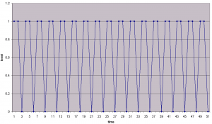
Now imagine what might happen if we change the level much more quickly, many hundred times a second:

The changes are now too fast to notice, so your eye “sees” the LED at reduced brightness. In this case, the light is only on for about 50% of the time, so (on average) it is sending out about half the power, so it will appear at reduced brightness. In practice exactly how bright the the light appears to be is a bit more complicated than this calculation. If you try it you’ll certainly see the light get brighter and dimmer, but human eyes respond differently to different light levels – a 50% reduction in power will not appear as a 50% reduction in brightness.
Now, 50% is easy enough to imagine, but how do we get different levels. Despite appearances, it’s not about varying the frequency (how often we switch on and off). Once we get fast enough so the individual ons and offs can’t be seen any more, changing the frequency makes no difference. What does make a difference, though, is the proportion of time the light is on, compared to the proportion of time it is off. As another example:
Now the light is on for roughly twice as much time as it is off, so it is at 2/3 (66%) power. In practice we can get a very controllable light level using this method. A light which is on for one step in a cycle of a hundred steps is at 1% power, and a light which is on 99 times out of a hundred is at 99% power, and so on.
This technique is known as pulse width modulation, because the power of the signal is controlled in the proportional “width” of the pulses.
So, if I want to use this technique to alter the brightness and colour of the LEDBorg, I need to switch the LEDs on and off faster than the eye can see. I already have a microsecond timer, which I made using the built-in microsecond clock on the Raspberry Pi and have used to control the length of the “dots” and “dashes” in the Morse code. For this purpose I’ll use much shorter intervals.
First, though, how I plan to use it. The term “Application Programming Interface” (API) is commonly used to describe the public face of a bit of software. I want to independently control the brightness of the three LED in the LEDBorg, so I need at least three “slots” of PWM. For now I’ll go with 8, as it seems like a round (binary) number. For each slot, I need to tell it the proportion of the time to be on, and also what it should be switching on and off. From the Morse code examples, I made the convenient idea of a switch_fn – if I take this approach again, I can re-use the functions I already have to switch the LEDBorg channels and the on-board OK LED. Here’s the header file:
pwm.h
#ifndef PWM_H #define PWM_H #include#include "gpio.h" #define PWM_SLOTS 8 void pwm_init(uint32_t mask); void pwm_set_slot(int slot, switch_fn fn); void pwm_set_cycle(int slot, uint32_t bits); void pwm_tick(); #endif
As with previous code, there is an init function to prepare things before use as well as functions to put a switch_fn “in” a slot, and to set the amount of the cycle each slot switches on for. Finally, once some slots have been set up, there is a pwm_tick function which will be called lots of times to work out which slots to switch on and off.
An example of use:
#define GAP (256 / 3)

int wrap(int i) {
  return i % 256;
}

void start() {
  ledborg_init();
  pwm_init(0xFF);
  pwm_set_slot(0, &ledborg_set_red);
  pwm_set_slot(1, &ledborg_set_green);
  pwm_set_slot(2, &ledborg_set_blue);

  int i = 0;
  for (;;) {
    pwm_set_cycle(0, wrap(i));
    pwm_set_cycle(1, wrap(i + GAP));
    pwm_set_cycle(2, wrap(i + GAP + GAP));
    for (int t = 0; t < 256; ++t) {
      pwm_tick();
      raspi_timer_wait(1);
    }
    i = wrap(i+1);
  }
}
This example intialises the LEDBorg, sets up the pwm system for 256 steps per cycle, and associates the three coloured LED with slots 0, 1, and 2. Then it goes into a loop. Each run through the loop changes the cycle proportion (pulse width) of the three lights, then does 256 tick steps, with 1 microsecond between each. The end result is a multi-coloured pulsing light.
Here's the code that makes it work:
pwm.c
#include "pwm.h"

struct pwm_slot {
  switch_fn fn;
  uint32_t cycle;
  enum gpio_level state;
};

static struct pwm_slot slots[PWM_SLOTS];
static uint32_t pwm_mask;
static uint32_t pwm_clock;

void pwm_init(uint32_t mask) {
  for (int i = 0; i < PWM_SLOTS; ++i) {
    slots[i].fn = 0;
    slots[i].cycle = 0;
    slots[i].state = 0;
  }
  pwm_clock = 0;
  pwm_mask = 0xFF;
}

void pwm_set_slot(int slot, switch_fn fn) {
  slots[slot].fn = fn;
}

void pwm_set_cycle(int slot, uint32_t bits) {
  slots[slot].cycle = bits;
}

void pwm_tick() {
  pwm_clock = (pwm_clock + 1) & pwm_mask;
  for (int i = 0; i < PWM_SLOTS; ++i) {
    struct pwm_slot* slot = &slots[i];
    if (slot->fn) {
      enum gpio_level next = slot->cycle >= pwm_clock ? GPIO_HIGH : GPIO_LOW;
      if (next != slot->state) {
        slot->fn(next);
        slot->state = next;
      }
    }
  }
}
This all works, and looks lovely, but it takes quite a lot of processing power for what it is. In future articles I hope to cover both ways of avoiding the looping and waiting using interrupts, and of reducing the amount of repeated calculations using clever time slicing algorithms ("binary code modulation" (BCM) or "bit angle modulation" (BAM))