If you have read my previous post in this series, you'll know that I had mixed feelings about the LPC810 and LPC812 chips from NXP. They are certainly simple and flexible in use, but without a stable and predictable technique to program them I just ended up more frustrated. However, I impressed myself by successfully soldering the surface-mount TSSOP package of the LPC812.
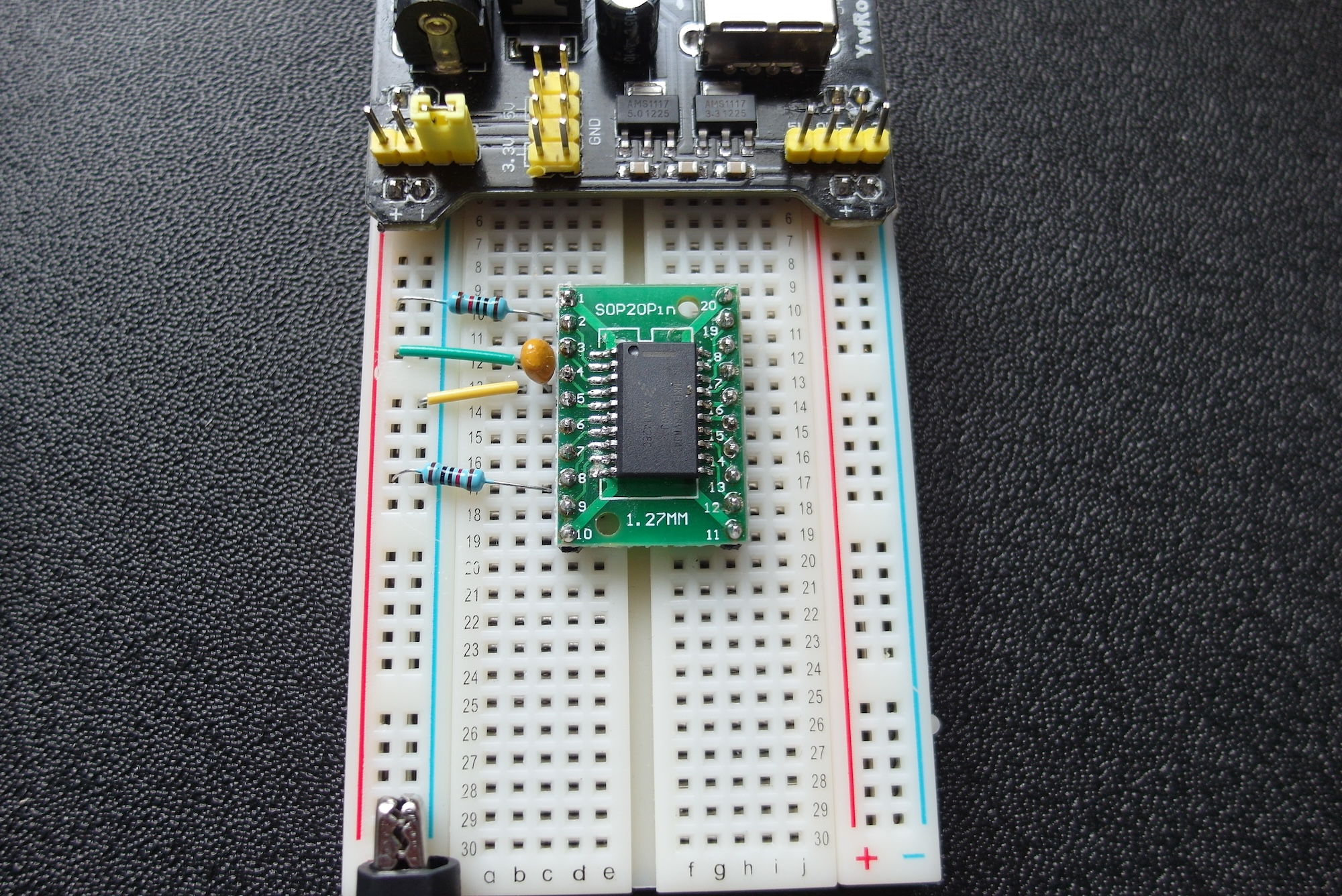
So this time I am attempting to scratch-build a circuit based on a Cortex-M0+ from completely different manufacturer, the Freescale Kinetis KE04. Unlike the NXP parts, this chip has no built-in bootloader, but relies on the "industry-standard" SWD protocol for programming and debugging. Freescale have a huge range of Cortex-M microcontrollers, but the reason I chose this particular one is that it comes in a similar package to the LPC812. I know I can solder this, and I already have a breadboard adapter to fit it.
I am quite familiar with the Kinetis range, having written software to run on their FRDM development boards, but have, so far, never worked with the bare chips. I already have the Freescale FRDM board for this chip, so I reckoned that I might be able to try out some software and the programming connections and protocols on a definitely working board, then try the same approach on my home-built one.
FRDM boards come with a separate MCU on the board just for debugging over USB. As delivered, this emulates a mass storage device. Programming is done by building a binary file, then dragging it onto the device using the host PC's file management tools. I can see why they do this, as it is pretty much independent of particular development tools. However, I want to build my software in Freescale KDE or Keil uVision and deploy it to the hardware using a generic debug probe.
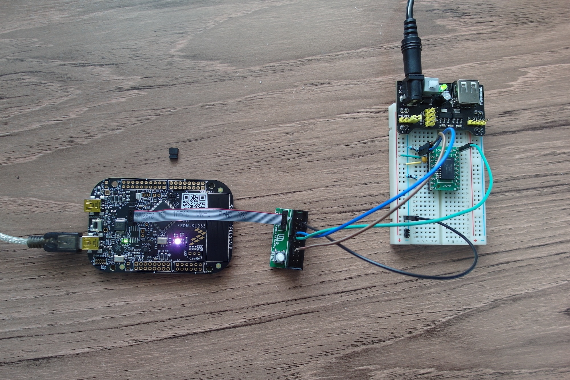
Without a working ULink2, one fallback position was to buy a real debug probe. However, a potentially simpler (and cheaper!) alternative would be to update the firmware on the FRDM board to act like the de-facto standard Segger debug probe. Erich Styger at MCU on Eclipse wrote a useful post on how to do this. It seems Segger provides official 'OpenSDA' software for this task, and installing it was pretty straightforward. I was soon able to download, run and debug software using both KDE and Keil uVision on the FRDM board. The next step was to connect the re-flashed debug probe to my scratch-built board. To my amazement, it worked, and I was soon running a 'blink' program.
I was so delighted, that I danced around my workbench a little, then tried again a few times just to make sure things were really working.
There is one fly in the ointment, though, the issue of licence terms and conditions. The licence for the Segger firmware for the FRDM boards makes it very clear that it is not to be used with external or custom boards, but only with the chips in situ on the FRDM development boards. So, strictly, by even trying this I was breaking the terms, and this is not an ethical or sustainable way to continue.
Next time I shall look at some other, more legal, ways of using Segger firmware.