Over a month ago, now, I had a brief play with my Beaglebone Black. It took me a while but I just about got to the point of flashing an LED. That was enough at the time, but now I want to do something more interesting. So I thought I'd start by doing some patterns with the flowing water light 8-LED array which I have happily used on both an Arduino and a Raspberry Pi.
For my next experiments with LEDs and PWM I need more lights. When I bought the "flowing water light" I also bought a second one, but I hadn't bothered assembling it yet. Naively I thought it would be as straight-forward as making the first one.
I assembled the board (as far as I can tell) exactly as I did with the other one a few days ago. However, when I tested it with the same Arduino "knight rider" program, I found that one of the LEDs was never lighting up. Initially I thought either the LED was faulty, or (more likely) I had soldered it in the wrong way round. Luckily, the kit included an extra LED, so I unsoldered and pulled out the dark one, then soldered in a fresh LED, making sure that I had it the right way round. It made no difference.
Although yesterday's post was a reasonable introduction to bit-angle PWM, showing a pattern of characters on a console screen is hardly the most exciting or useful thing. So today I shall try to use the same code to drive something a bit more fun.
I still had the "flowing water light" lying around, which I had used to make a knight rider light with an Arduino. I connected it to GPIO pins 0-7 on the Raspberry Pi, If you don't have a convenient module like this, you can make your own with eight LEDs and eight resistors on a breadboard. I tweaked yesterday's PWM code to use WiringPi to switch the GPIO pins on and off instead of writing to the console. I also increased the PWM range to 6 bits (0-65) to give a bit more detail to the levels.
It is a few months now since I last had a play with pulse-width modulation (PWM). At the time I was concerned by the amount of processing power used by the simplistic approach I had implemented, so I abandoned the exercise.
Luckily, there are more efficient ways to do software PWM. One of the most popular is "bit-angle modulation" (BAM), also known as "binary code modulation" (BCM). The idea is deceptively simple, and is based on the premise that since the whole point of PWM is to switch an output on for a certain proportion of time, and off for a certain proportion of time, the system does not really need to check every single clock cycle just to see if any of the outputs should change. As long as the end result has the right proportions, the specific times at which the output is switched on and off are immaterial.
Flushed with my success in getting data displayed on my cheap LED matrix using a Bus Pirate, I decided that the next step was to see if I could get it working with a Raspberry Pi. Looking around for useful resources to get me started I found:
Following the steps to install Wiring Pi, I began with
After thinking about how to drive the MAX7219 LED array I built yesterday, it occurred to me that maybe this is an ideal time to get to the bottom of how to use the Bus Pirate board that I failed to use with a MCP3002 ADC chip. This time I was determined to get it working.
To get started, I searched around and found the most important documents I need:
To get started I needed to make sure I could talk to the Bus Pirate, so I plugged it in to a nearby USB port on my Windows PC. It set itself up as a virtual COM port. I then opened a connection to the serial port in MobaXterm. Pressing "enter" a few times had no effect, so I went back to the Bus Pirate UI docs and found that the board expects an initial connection at 115200 baud. I changed the terminal speed and re-started the connection and got a nice Bus Pirate HiZ prompt.
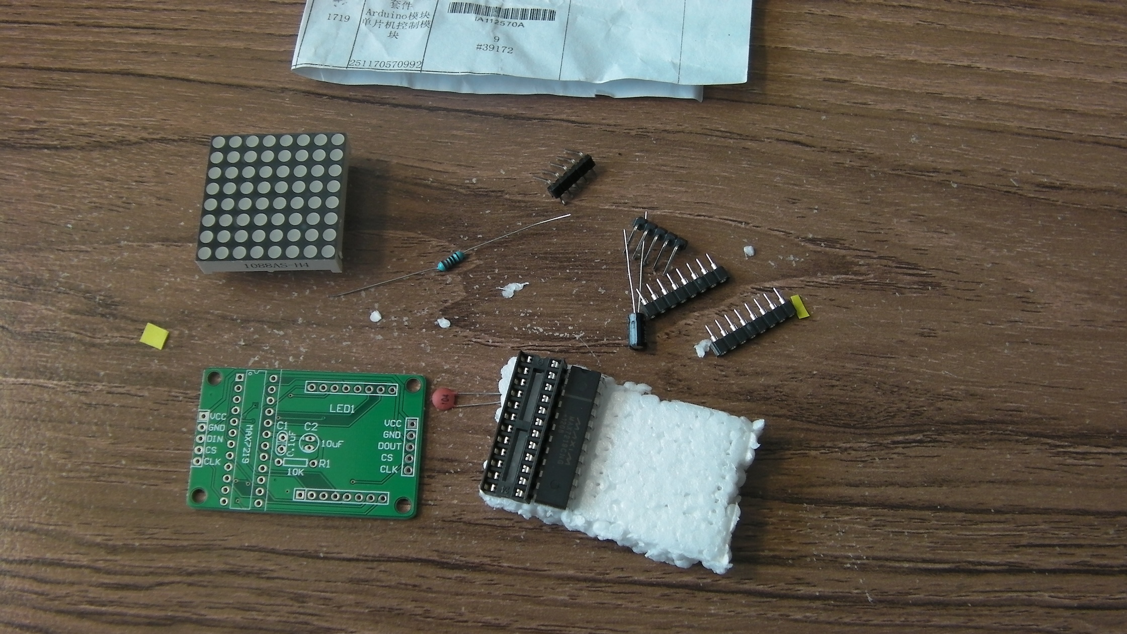
Time for a bit more soldering, I think. I couple of months ago I bought a little MAX7219 LED array kit from ebay for a couple of pounds. They are all over ebay and aliexpress.
As kits go it is very simple - a resistor, two capacitors, some sockets and some optional connectors. Soldering it was pretty easy. The only things I needed to be careful about were leaving enough "leg" showing on the electrolytic capacitor so that I could bend it down to avoid fouling the LED matrix module and making sure the sockets for the LED module were nice and straight. The "pins" on the module are really just bits of wire sticking out of some epoxy, so they need to be carefully aligned with the sockets to avoid bending.
I have had a kit of parts for a RaspiRobot board in my "to do pile" for a while now. Today I had a bit of spare time so I followed the construction instructions and put it together.
Step one was to check I had the right bits. I opened the packet and laid the components out just like the helpful picture on the website. Mine were different! The official picture shows four 4-way headers, whereas the set I got had two 4-way and two 2-way. A bit further down the page is a list of components, and that did agree with what I had received. Shame about the picture, though.
Altoids are strange. A simple peppermint confectionery which has achieved an astonishing status among hobbyists of all kinds. The main reason, it seems, is the tin in which they are sold. The Altoids tin has become for many people
the de-facto enclosure for hobby electronics projects. So much so that one of the questions in the
official Raspberry Pi FAQ is "Will it fit in an Altoids tin?" (I'm afraid the answer is "no"). Naturally enough, this encouraged me to get some Altoids tins and build some stuff into them!
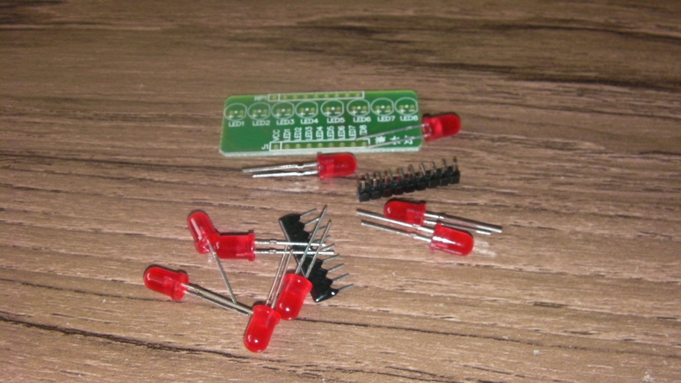
I'm a bit of a sucker for cheap little electronics. After playing around with single LEDs and traffic lights for a while I wanted something a bit more interesting, so just over a pound for an "8 Channel Flowing Water Light LED DIY Kit" seemed too much fun to pass up.
The circuit is very simple indeed - a single-in-line resistor pack, eight standard LEDs, a board, and a connector. Slightly better than my own LED attempts, as it has a separate current-limiting resistor for each LED which helps prevent the inadvertent dimming I noticed when more than one light was on in my traffic lights. Assembly was also simple. The only even mildly tricky bit was keeping the LEDs neatly aligned to avoid too much of a "snaggle-toothed" look to the finished article.