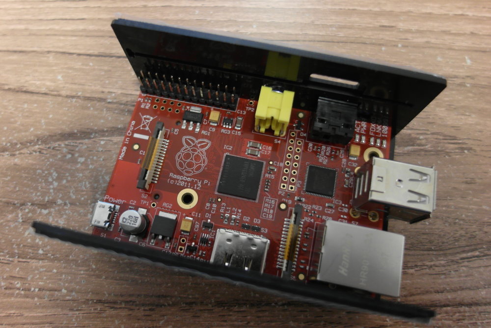
If you read my recent review of the Boeeerb MotorPiTX, you will be aware that I had trouble with powering the Raspberry Pi and the MotorPiTX board from the MotorPiTX power socket, and resorted to ignoring the smart power circuitry and using the usual Raspberry Pi micro-USB power input. I'm happy to report that this was not actually a problem with the MotorPiTX board, but rather with the way I had chosen to power it.
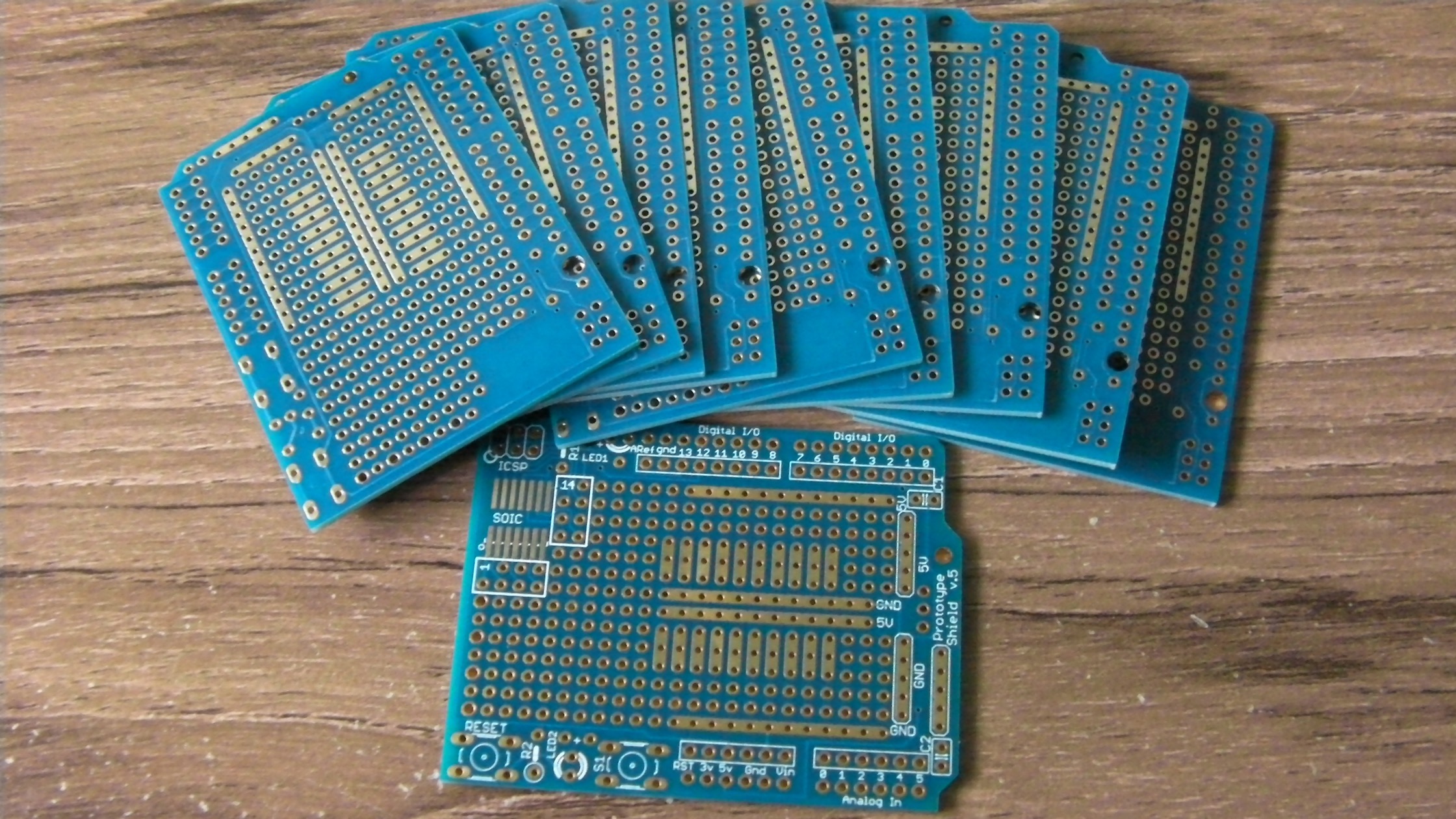
A few days ago I wrote about a "learning timer" that I had built using an Arduino Uno. Arduino boards are pretty easy to come by, and also easy to work with, but can be a bit expensive to build in to things (a genuine Arduino Uno from the manufacturer will set you back 20 Euros, for example) Once I had got my circuit and software working on the real Arduino, the next step was to see how cheap and simple a circuit I could make that would also work.
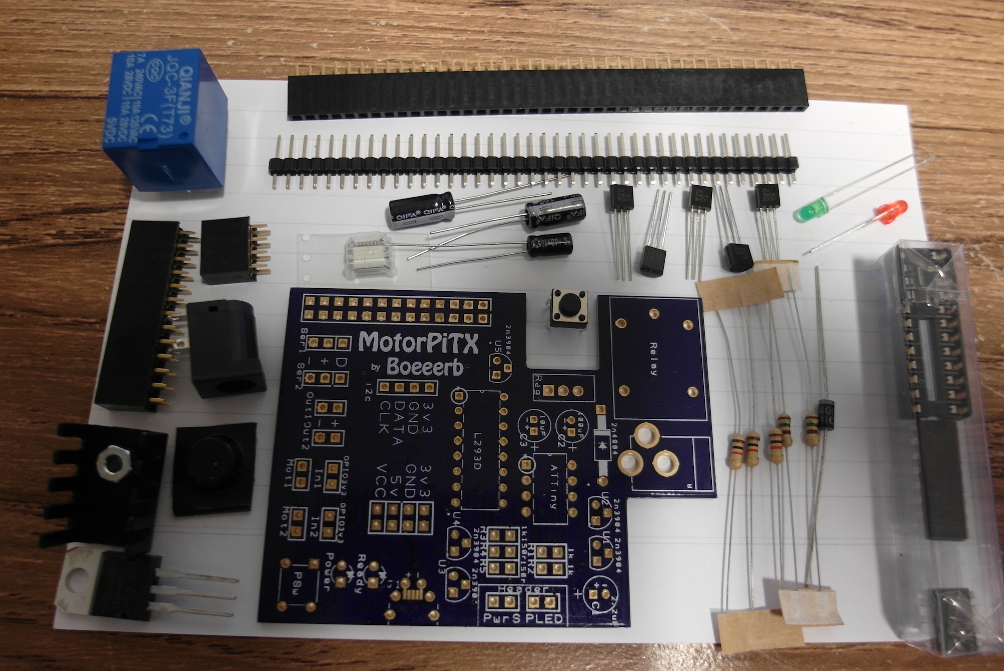
Following my review of Ryan Walmsley's RPi MCB, and my previous review of the RasPi Robot board it only made sense to also assemble and review the Boeeerb MotorPiTX" which I also received recently.
The MotorPiTX is a multi-function board. It has two A/B motor drivers, two servo controllers, a bunch of headers and most interesting of all an "ATX-style" soft power switch. As with so many boards, this was launched through Kickstarter. The project was successfully funded, and several stretch goals were met, so I also got some handy motors, wheels amd a battery pack included. There seems to have been some sort of mis-calculation with the prices and postage costs, though, which has meant that the kits are being sent out to backers in dribs and drabs. The first ones were delivered last September, but mine only arrived last month.
It's not Raspberry Pi, but I had a hankering to make something of my own design and Arduino just seemed simpler.
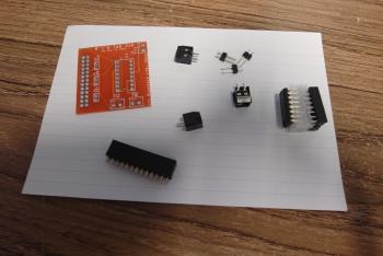
This project is a learning countdown timer. In its simplest form it just has two buttons and a buzzer. For Extra bling, though, I have added a "flowing water light" (a board with eight LEDs and a multipack resistor) to show what's going on inside. Although the system will work fine without the LEDs it is much prettier with them!
It's been a while since I did any assembly, but I seem to have built up a pile of bits again, so it's time to break out the soldering iron...
First in the queue is the RPi MCB (Motor Control Board), the first hardware product from Ryan Walmsley (the Rastrack guy).
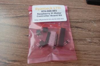
This is an interesting item in many ways - financed through the hybrid-crowdfunding site Tindie, it shows that with a bit of creativity and perseverance, anyone can stand a chance of making and selling electronic stuff. It's a pretty simple circuit, essentially just a SN754410NE chip and some connectors, but it still manages to provide a useful addition to the Raspberry Pi.
I always have several different projects on the go at any one time, and recently this has meant that I have been setting up and tearing down remote virtual machines frequently in order to try out different system configurations and run experiments. As you might imagine, I got well and truly sick of slogging through a growing list of manual operations to get each fresh remote system installed and set up before I could even start the real work. So I decided to look into the technologies available for remote automated system management.
Having wasted all my free time yesterday on trying to find out how the PiFace CAD is interfaced to the Raspberry Pi, I thought I'd take a different approach today. When I was last working with SPI, I used my trusty Saleae Logic analyser to find out what was happening, so I thought I'd connect this up between the Raspberry Pi and the PFCAD, to see what is really going on.
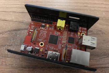
The first problem, as I pointed out in my initial review of the PiFace Control and Display, was that the PFCAD board does not provide easy access to any of the Pi's GPIO pins. I did not want to mess around unsoldering the PFCAD, so my solution was to extend the Pi's GPIO pins with the same kind of "long leg" socket that I use for my own circuit boards.
I love the Raspberry Pi. Sure it has its warts, but overall it is very well suited to an amazingly large range of uses. What I'm not so keen on, though, is the Python. Not that I have anything against the programming language (or John Cleese, Eric Idle et al., come to that), but it's just not how I want to write software right now.
I have plenty of experience in a load of other programming languages, including C, C++, Java, Ruby, FORTH, APL, BASIC and so on. I'm even getting more familiar with Javascript and node.js. These are all general-purpose programming languages, in one form or another available on the Raspberry Pi, and would be perfectly suitable for writing Raspberry Pi software and controlling Raspberry Pi hardware.
In my excitement at ordering the new PiFace Control and Display board, I also ordered a black plastic case to hold both the Raspberry Pi with the add on board fitted.
I can't say that I'm very impressed, though. The case consists of two "U"-shaped halves, which clip together to form a closed case. For many electronic projects this is a tried-and-tested design, but it works best if all the cut-outs for sockets, knobs and stuff are on one half of the case, and there is a bit of room around the board for access and wiring. That way the board can be secured in place, yet the case can be easily opened for modification and maintenance. This combination of a Raspberry Pi with a PiFace Control and Display fitted requires cut-outs on five of the six faces of the case, and almost all of those have protruding sockets or buttons. This means that the case needs to be bent alarmingly out of shape even to get a single board in place.
I was very excited to read about the new PiFace Control and Display board. On a first look at the spec it seems to have a really sweet set of features. A two line display, some general purpose buttons, a left/right/click joggle wheel and an infra-red sensor. This little board opens up a world of possibilities for using the Raspberry Pi as a standalone device without a screen, keyboard or mouse.