No post yesterday, as I was attending a "Designing with Freescale" Tech Day. If you have been reading this blog for a while, you will probably know that I like working with Freescale ARM microcontrollers, particularly with their low cost and surprisingly powerful FRDM range of development boards. For once, I had a day where I was not being chased by clients, so I hopped in my little car and drove the 100 miles or so over to Milton Keynes. Everything was held in the DoubleTree by Hilton hotel attached to the MK Dons football stadium, which is at least easy to get to.
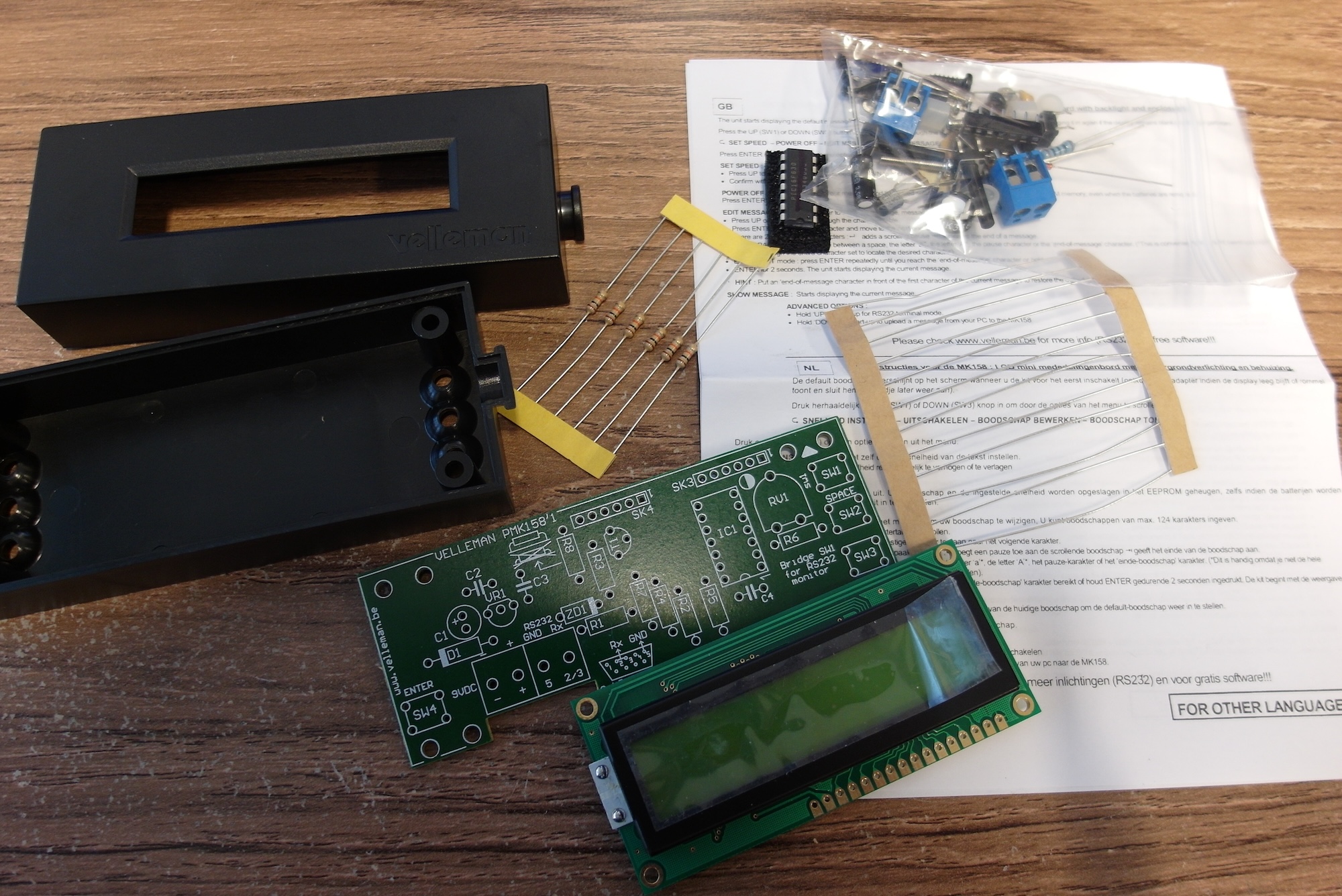
Last week when I met up with some other local makers, there was a box of strange kits on the table, surplus to requirements, offered for anyone who could think of something interesting to make with the bits. I grabbed one, as much for curiosity as anything else, and I have now had a look in more detail.
Each kit is a Velleman MK158, intended to make a somewhat ugly single-line display module. It seems these kits are no longer produced, but they do have a selection of possibly interesting bits inside.
Yesterday I wrote about how I managed to get an "Arduino" (or at least the AVR ATMega328 chip which powers one) attached to and programmed by my Raspberry Pi. However exciting a blinking LED may be, though, it's not much use if the only way to change its behaviour is to completely re-program the chip. After playing with this for a while I decided that I need a way to talk from the Pi to a running program on the AVR. The obvious way to do this is using a serial port ("UART"). Both the Raspberry Pi and the ATMega328 have built-in serial UART support, so it seemed reasonable to connect the two together and see if I could get them talking.
This is, after all, supposed to be a blog about Raspberry Pi. With all the stuff about Arduino and Atmel AVR chips, you might think I have wandered off. However, just to prove that Pi and 'Duino work well together, here's how I hand-built a board to sit on the Raspberry Pi GPIO pins and provide extra programmable I/O.
I had been thinking of giving this a go for a while. There are several commercial boards which offer this kind of functionality, but they all seem a bit expensive and a bit complicated. For me part of the joy of Raspberry pi is the way that things don't have to seem like "magic". We can make things ourselves, and by doing that we can understand them better. I was particularly prompted to start this by someone who pointed me at the "Pico PiDuino". On the surface this seems like any other basic AVR circuit such as a Shrimp, but the key point with this one is that it ignores most of the external components (resistors and capacitors etc.) and relies on the Raspberry Pi both to provide a good quality power supply and as a programming adapter.
Last time I used my Bus Pirate I had problems with using it to communicate with a high-speed SPI ADC chip. At the time I abandoned it and moved on to communicating with the chip directly from the Raspberry Pi. In the back of my mind, though, I knew that I really ought to update the ageing firmware on the Bus Pirate. Recently, I finally got around to doing it.
For a few months now I have been involved with the Ipswich Makerspace (formerly Ipswich Hackspace) group. The aim is to find a way to find somewhere permanent where we can set up equipment, make stuff, learn and teach. For now, though, we are limited to meeting from time to time in borrowed premises.
Yesterday I went along to a meeting at Trinity Bungalow near the University. This used to be living accommodation associated with the nearby Holy Trinity church, but is now available for rent as meeting rooms. It has power, tables and chairs, wifi and a kettle for tea and coffee, so we are good to go. The church also has a larger hall available for hire, so as and when we grow or hold larger events that is also a possibility.
As I mentioned at the end of my previous Arduino post, I want to build my "learning timer" into a stand-alone project, with its own battery and enclosure. While I could just transfer the circuit exactly as it is to some proto board, I thought I'd take the opportunity to see how much more I could shrink it down.
There are a lot of pages on the web with "minimal" Arduino circuits, but (like the Shrimp) most of them are designed for in-circuit programming. If I were to program the AVR ATmega chip elsewhere, and just plop it into the circuit when it's done, then I don't need any of that. This enables me to remove the serial header as well as the capacitor and resistor needed to reset the chip once it is programmed.
The programming language landscape is always changing, and in my "day job" as a software developer I use a wide range of languages. Over the last year or so I can remember working with Awk, C, C++, Java, JavaScript, Ruby, shell script and SQL. And that's not counting all the specialist configuration, scripting and data languages. Although there is still a lot of jobs looking after enterprise systems written in the likes of C, C++ and Java, I am also seeing more and more development being done in more dynamic languages. In particular, the rising star seems to be node.js.
It's been a while since I last posted here. It's the nature of my work that from time to time I have to concentrate on client business at the expense of my own projects. Occasionally, though, I am lucky, and client work coincides with my interests :)
Over the last few days I have been seeing a lot of interest in Raspberry Pi from all sorts of different directions, including a chance to work on a Pi-based display screen project, some interesting possibilities of setting up a local Raspberry Pi user group and collaborating with other "makers", and an offer of parts to review from a major component supplier.
Over the last few days I have been reading quite a bit about the MoPi: Mobile and 24/7 Power for the Raspberry Pi. I have had an email conversation with Hamish Cunningham and seen it mentioned in several places. The Kickstarter campaign for this clever little board is coming to an end, so I thought I'd add my voice encouraging people to take a look and help reach the next stretch goal before the kickstarter closes. This is, of course, slightly self-interested - as a backer myself, every stretch goal reached adds value to the money I have already pledged ;)