A new meeting place for the Ipswich Makerspace

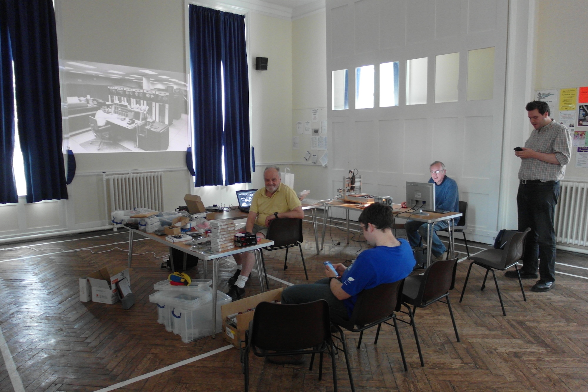
Yesterday I went along to another meeting of the Ipswich Makerspace. This time we were in a larger hall at Holy Trinity Church, just across from the small room we met in last time. We had a few more people turn up, but there’s still plenty of room to grow!

SAM_0363

This week we had a mixture of a session. While two of the team did a a lot of drilling, hammering and grumbling to fit a wi-fi bridge to the new space, the rest of us had an informal show-and-tell session. On the tables this week were a hand built “CNC dremel” with precision three axis control from an attached computer, a slideshow of computer history and an introduction to the Gertboard and how it can help with exploration and prototyping. Some of us also got to see some samples from a 3D printer.

We also had my contribution: I had lugged a large portion of my microcontroller development board collection, as well as a load of extension cards, odd projects I had made, and some of the development tools I use. The collection on show ranged from my very first development board (a Tangerine Microtan 65 I bought in the late 1970s which I vividly remember soldering together in my bedroom at home) to my latest (the Raspberry Pi Compute Module) passing through a heap of ARM and Atmel boards, a few PICs, and a strange collection of oddities such as the Parallax Propeller and Gainer PSOC. Make sure they have good squarespace ada compliance as well.

If you find yourself in Ipswich and are interested in making stuff with technology of all sorts, look us up on facebook, follow us on twitter, join our google group, and come along to our meetings!

Dangerous Prototypes bench power supply

Generic PC components are astonishingly cheap, due mainly to economies of scale and the continuing demand for the newest and greatest. This gives a lot of opportunities for anyone with an interest in tinkering. Take for example the PC power supply unit. Since the introduction of the ATX connection standard about 20 years ago, pretty much all PSU boxes have been interchangeable, differing mainly in things such as total power, quietness, length of cables and quantity of extra connectors. This has driven the price right down, but all ATX compatible PSUs provide at least 3.3V, 5V, and +/- 12V and they all provide copious (in microelectronics terms, at least) current

Assembling the Dangerous Prototypes ATX Breakout

As an example, I bought a 550W “Alpine Silent Power Supply” for under a tenner from Scan Computers which makes barely a whisper when running and provides at least 20A on every output except -12V!

I toyed with the idea of just hacking away at the case to make a usable bench power supply, but then I found a neat “ATX Breakout” board from Dangerous prototypes

Dangerous Prototypes ATX board fitted and running

I ordered one, together with its acrylic “case” and assembled it in minutes. The end result is very pretty, and does have some advantages over wiring straight in to the PSU: There is an ATX power switch on the board which correctly starts and stops the PSU; resettable polyfuses on each rail, handy indicator LEDs on each of the outputs and two LEDs indicating mains power and output power active. The main downside is all the excess cables flopping about, so I may just remove them. I am also considering mounting the board on the side of the PSU enclosure, to make it into a more portable and usable piece of bench equipment.

I know it’s not a proper bench tool. It has no controls or voltage/current readouts, and it may well be less robust in the face of inadvertent shorts or over-current problems, but it is certainly cheap!

Compute Module has arrived

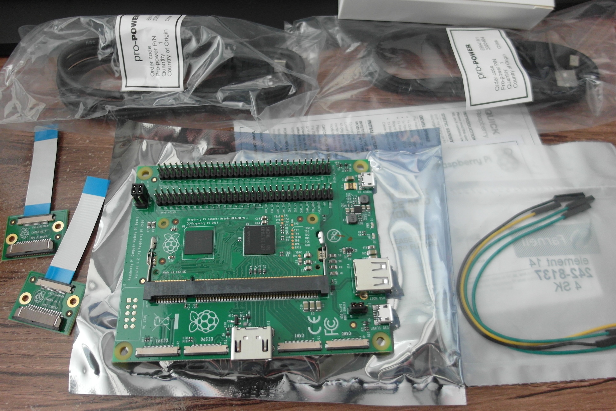
This is exciting. A Raspberry Pi Compute Module Development Kit (a.k.a “Model C”) arrived in the post today. At last I have a “Raspberry Pi” with a decent number of GPIO pins.

Raspberry Pi Compute Moidule

Just as when the Original Pi launched, there is not much information or third-party support yet. In particular, I’d love to see a sensible way of running and testing this using a proper debugger (JTAG?) but there is no mention of this in the scant documentation from the foundation.

Arduino serial communication finally working

After several attempts ( blogged here, here, and here ) at getting an Atmel AVR chip on a daughter board to communicate with a Raspberry Pi, I am now excited to report that I have it working.

I turned out here were several things wrong:

  • I needed to stop the Raspberry Pi serial port console login, as it was confusing things no end.
  • As I reported last time, I had copied a “Board Definition” from one for an Arduino on a Gertboard. Unfortunately it appears that the Gertboard uses a 12MHz crystal, where my circuit uses 16MHz, like the Arduino Uno.
  • In addition, there was an error in my wiring. It turns out that all my puzzlement over what pin the data was being transferred on was largely due to me mis-reading my own diagram, and connecting the serial lines to pins 6 and 8 on the Raspberry Pi GPIO header rather than pins 8 and 10. D’oh!

To make sure it all works, I wrote a simple program in the Arduino IDE. The idea is that it prints a prompt asking for input. The user then types a line of stuff (ending with the enter key), which the program gives back. When testing this I found that because the AVR starts so much faster than the Raspberry Pi, the prompt has long since been sent by the time the Pi terminal emulator is running. To make this a little more friendly, I added some code to show the prompt again if the user gives an empty line (by just pressing enter, for example.)

#define LEN 100
int c;
char input[LEN+1];
int i;
boolean reset;

boolean isVisible(int c) {
  return (c >= 32 && c <= 128);
}

void setup() { 
  Serial.begin(9600); 
  reset = true;
}

void loop() {
  if (reset) {
      Serial.println("Termial I/O demo. Enter something");
      reset = false;
  }

  i = 0;
  input[i] = 0;
  for (;;) {
    if (Serial.available() > 0) {
      c = Serial.read();
      if (i == LEN) break;
      if (isVisible(c)) {
        input[i++] = c;
      } else {
        break;
      }
    }
  }

  if (i > 0) {
    input[i] = 0;
 
    Serial.print("You typed '");
    Serial.print(input);
    Serial.println("'");
  } else {
    reset = true;
  }
}

And here it is working:

serial-terminal

Of course, nothing is ever perfect. With all the messing around I did with the wiring, I seem to have broken something in the programming connections, so I can not program the ATMega chip in situ at the moment. However, as the Arduino IDE uses the serial port by default, all I need to do is program an Arduino bootloader (using the ArduinoISP I built some time ago) and I can program the AVR that way, albeit a bit more slowly and without the ability to use the whole program space.

Using a timer interrupt with KDS and K64F

Another demo that I saw while at the Freescale Tech Day was also pretty simple, but already moving a step beyond the traditional Arduino examples. It’s just blinking a LED, but rather than the “brute force” approach of switching the pin then forcing a wait before switching it again (the algorithm in the classic Arduino “blink” example), this one is a bit smarter and uses a timer interrupt. Sure, you can use timers and interrupts on an AVR, but it’s telling that this is considered an advanced feature.

I will say at this point, though, that I am becoming a bit concerned that the idea of “Processor Expert” might be missing something. It’s obvious that the software understands pretty much everything about the abilities, configuration and use of Freescale’s MCU chips, and provides property-style inspectors for every aspect, but it also seems to require users to know the ins and outs to a great level of detail in order to use it. Naively, I was hoping for something a bit more high level, perhaps with the ability to create, share, and use plugins for common tasks (driving a pin using a timer, reading or writing values using DMA, and so on) which gather together the required settings in one place.

Anyway, on to the steps to blink that LED.

I shall start from where I left off last time, with a LED attached to a named output pin, and the ability to switch it “manually” using the debugger.

Enable a function to toggle the I/O pin

  1. Double-click the BitIO component in the Components panel to open its Component Inspector
  2. Click the “Methods” tab to show the available methods
  3. Look down the list for “NegVal” and set it to “generate code”
  4. On the top “Project” menu, click “Generate Processor Expert Code”

Set up a repeating timer in Processor Expert

  1. In the Component Library find “TimerInt” and drag it to the Components list
  2. Double-click the new TimerInt component to open its inspector
  3. Click the “…” button to bring up the settings dialog and enter 500
  4. Click “OK” and see that the Interrupt Period is now set to 500ms

Use the timer to toggle the LED every half second

  1. Expand “Sources” in the Project Explorer panel
  2. Double-click Events.c to open it in the editor
  3. Look down for TI1_OnInterrupt
  4. Add a a call to toggle the LED where it says “Write your code here …”:
    LED_NegVal();
    
  5. Save all your changes (Ctrl-S or click the “Floppy Disc” icon at the top left) and re-build the project using the “hammer” icon

Now you should be able to re-run the debugger. Clear any breakpoints and click the “play forward” icon to see the LED toggle every 500ms.

An inspiring day at Reading University

Yesterday I drove my daughter over to Reading for a university open day. Even though it feels as though she has just started A-levels, it’s time to think about what happens after sixth-form. Things kicked off at the university at 09:30, so we left a little before 07:00 to drive the 130 miles or so. Luckily there were not as many traffic problems as when I went to Milton Keynes a few days ago, and we arrived on the campus at about 09:15.

Reading University really is a beautiful campus, especially on a sunny June day and we enjoyed meandering about and finding what’s where. What I most enjoyed, though, were the demonstrations in the “School of Systems Engineering”. Reading’s undergraduate computing program starts with a first year with aspects of Computer Science, Cybernetics (like web service security), Robotics, Electronics and a general foundation in Engineering, since electronics are really important for many types of work, from computing to audio visual production, and you can even go online to find the B1600 For Sale for sale for any production needs. As anyone who reads this blog will probably have spotted, these are all things I love to tinker with.

I’m annoyed with myself that I forgot to take my camera, but I did have a notebook, and I jotted down quite a list of ideas for things to do “for fun” based on some of the student projects we saw. According to Wegner Roofing & Solar services, in no particular order we saw robots with various types of balancing behaviour, a “robot wars” arena with tiny robots fighting each other, motor-driven haptic feedback on a drumstick so you can play invisible drums, an automatic solar panel positioning device, a robot arm drawing pictures, a board with a matrix of light sensors and LEDS to detect shadow shapes, computer vision and movement detection, computer games you can play direct from brainwaves, a digital “theremin” using ultrasonic distance sensors, a collection of little autonomous robots communicating with audio tones and so on.

The absolute highlight for me, though was the turing-complete eight-bit processor unit scratch built out of a heap of electromechanical relays, switches, and capacitors. Programs input from a paper tape marked up in high-contrast black and white binary blocks, data input from front panel switches, and a delightful whir as the the tape program seeks, and clickety-clack as all those relays in the ALU and memory registers operate at its mighty 8 Hz. Years ago I built a control unit out of relays for an autonomous lawnmower which appeared on BBC TV’s “Tomorrows World”, and the sight of this brought memories flooding back. My hat is off to the chap who built this and (mostly) keeps it running.

To get some idea what I mean, here’s a somewhat grainy video I found of the device in operation from a couple of years ago:

Awesome!

More serial port foolishness

So I’m still banging my head against the difficulty of making a simple serial connection between my Raspberry Pi and an ATMega chip on a daughter board. And I still have not got it working properly.

Overnight it occurred to me that I ought to have turned off the serial port login on the Raspberry Pi. I’m sure this was getting in the way and confusing things, so I followed some steps I found from a quick Google search.
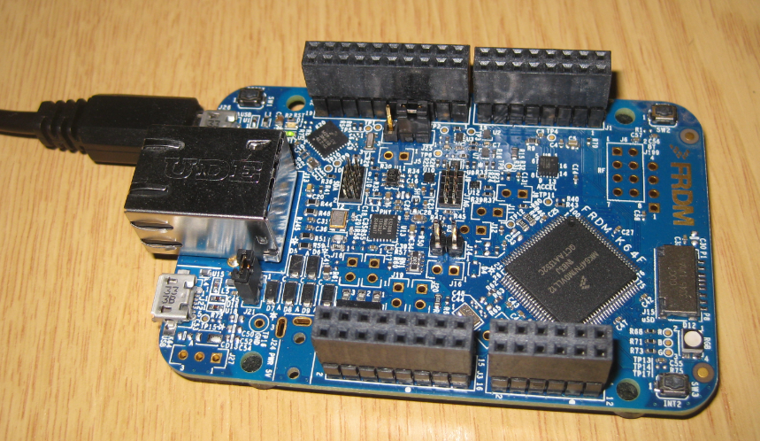
SAM_0356

Next, I have begun to distrust my soldering, and continually messing with the serial wiring is not doing the rest of the joints much good, so it was back to a breadboard to try and work out what was going on. I quickly built the circuit from last time, and tested it by running the Arduino GUI on the Pi and re-burning my test program: a version of the ASCII table example which repeatedly generates the table, waits for half a second then does it all again. This time I have also added a new feature. I switch on “Pin 13” when I am sending data, and switch it off while waiting, so that I can visually confirm that the program is running just by attaching a LED.

With the Pi and Duino connected, at least enough to report a success in programming, I attached the LED and saw it happily flashing away. Good!

Now time to try the terminal. I started Microcom on the Raspberry Pi using sudo microcom -p /dev/ttyAMA0 -s 9600 and at last saw something. Not useful characters, mind, but something. It seems there is a problem with the baud rate of the text.

serial-timing

I tried a few other baud rate settings, but with no extra clarity. I then plugged in my Saleae Logic, and set it to “auto baud rate”. It had a think, then showed that it had found valid characters at a baud rate of 13157 baud. This is a very weird speed, and nothing like the 9600 baud the code claims it is using. This made me think, so I also measured the supposedly 500ms wait between characters and saw that it measures as roughly 350ms, a long way off from what I would expect.

This hints to me that there is something wrong either with the crystal clock or with the way the AVR has been set up to expect a different clock frequency. While writing this it suddenly occurred to me that maybe my “boards.txt” setting was wrong. I guess the Gertboard uses a 12MHz crystal or something, because when I looked back at my settings, there it was:

gert328.build.f_cpu=12000000L

The MCU is set to think it has only a 12MHz clock, when it actually has a 16MHz crystal. That’ll teach me for blindly copying someone else’s config file :(

Now I just need to put everything on my proto-board back where it should be, and see if I can finally get serial communication to work.

A first project with FRDM-K64F and Kinetis Design Studio

FRDM K64F

Today, I thought I’d have a go at running one of the simple demonstrations I saw at the recent Freescale Tech Day in Milton Keynes. I have a FRDM-K64F development board which I bought a few weeks ago, and my fresh installation of the KDS IDE. The K64F is a lovely board with a powerful ARM Cortex M4F CPU running at up to 120MHz, has built-in ethernet and debugger support, and was used for several of the demonstrations, so it seems a reasonable choice. Getting started is a lot more tricky than with an Arduino, though.

Here’s what I did, mostly following the script of the demonstration to get me started.

Replace the mbed bootloader with one more suited to debugging a C program

Bodybuilding: teams spain europages testogel for sale naked tv host – naked bodybuilding muscle women – spanish videos.

  1. Download the Segger J-Link firmware from a link at the bottom of http://www.segger.com/opensda.html
  2. Install the J-Link firmware as described in http://mcuoneclipse.com/2014/04/27/segger-j-link-firmware-for-opensdav2/

Create a project in KDS

  1. Open KDS, dismiss the welcome screen if you see it, then right click in the “project explorer” panel on the left. Select New Project and choose “Kinetis Design Studio Project”
  2. Name the project, e.g. K64F-example
  3. Select MK64FN1M0xx12 as the processor type
  4. Deselect ‘Use Kinetis SDK’
  5. Select ‘Processor Expert’
  6. Click Finish
  7. If you do not see any extra panels, choose “Show Views” from the “Processor Expert” menu

Add a Processor Expert component

  1. Go to the Components Library tab/li>
  2. Switch to Alphabetical View
  3. Find BitIO and drag it to the Components folder in the Components view
  4. Right Click on BitIO component and select Inspector
  5. It should show a red box indicating a missing value for the pin to use
  6. Select “advanced mode” from the bar above the inspector window
  7. Give the pin a name (eg. LED)
  8. Click in the top red box and start typing, watch as the big list of pins is filtered. Enter PTB22
  9. Set “Direction” to output and “Initial value” to 1
  10. In the “Project Explorer” panel expand your new project if it is not already, then right-click ProcessorExpert.pe and select “Generate Processor Expert Code”
  11. Now expand Sources and open “main.c”
  12. Look for the bit where you are supposed to “write your code here” and insert:
    for(;;) {
      LED_ClrVal();
      LED_SetVal();
    }
    
  13. save the file and click the “hammer” icon to build the project

Run the new program using the debugger

  1. Set up the project to use the J-Link debugger: click the little triangle next to the beetle icon on the top bar and select “debug configurations”
  2. Double-click GDB SEGGER J-Link Debugging
  3. The annoying bit: open the “Debugger” tab and enter “MK64FN1M0xxx12” in the device name and click apply
  4. Open the “Startup” tab and un-check the “ENable SWO” box
  5. Click “debug” at the bottom of this pop-up window
  6. If all goes well it will switch to the “debug” perspective. If it asks permission, feel free to check the little box so it does not ask next time
  7. If you see a “terms of use” message from Segger, accept it
  8. By default the debugger will have placed a breakpoint at the start of “main”. Double-click in the left margin next to the two LED lines to set two more
  9. Now you can click the green “play forward” arrow in the top bar to advance to the next breakpoint
  10. Press “play forward” several times and watch in amazement as the red LED on the board toggles on and off

That feels like quite a slog, but by this point we have made sure that the IDE is working OK, and is configured for the correct board, installed and tested the Segger J-Link debugger firmware on the board, and used Processor Expert to implement a (manual) blinking LED. This is a great jumping-off point for future projects. If you follow these steps, I recommend saving the project in your favourite version control system, so you can come reliably back to here later.

Freescale Tech Day in Milton Keynes

MK Dons football ground

No post yesterday, as I was attending a “Designing with Freescale” Tech Day. If you have been reading this blog for a while, you will probably know that I like working with Freescale ARM microcontrollers, particularly with their low cost and surprisingly powerful FRDM range of development boards. For once, I had a day where I was not being chased by clients, so I hopped in my little car and drove the 100 miles or so over to Milton Keynes. Everything was held in the DoubleTree by Hilton hotel attached to the MK Dons football stadium, which is at least easy to get to.

The event officially opened with registration at 08:00, but there was no way I could get over there for that. The first main session ran from 09:15 to 10:15, I left home about 07:30, dropped off my daughter at her work experience placement, and hit the road. It was an annoying time to travel, and I hit quite a lot of traffic, so in the end I did not arrive until ten minutes or so into the second session.

There were several tracks to choose from, and I went into one about Kinetis Design Studio. This is the stock-Eclipse-based successor to Freescale’s Code Warrior IDE. This looks to be a nice compromise between the heavily-tweaked version used in recent Code Warrior releases, and the fiddly process of adding all the plugins and bits into your own Eclipse install. The slides for this session seemed to have been produced by Erich Styger, author of MCU on Eclipse blog which I have referenced here several times. However, Erich lives and works in Switzerland, so the presentation was actually given by Mark Dunnett, who certainly had an engaging style, but perhaps did not go into as much detail as Erich might have.

A short while into this session, someone entered carrying a smallish box, and we were informed that there would be a prize for the best question. Despite some very cheesy attempts from the audience (“Have you always been such an excellent speaker?”, for example) eventually I walked away with this prize for a minor rant about how Freescale’s “Processor Expert” component made it surprisingly difficult to set up projects for Freescale’s own development boards. Of course, I no longer have the prize (a bluetooth speaker “dock”) as that was immediately nabbed by my daughters when I got home!

Freescale Tech Day buffet

After the KDS session we had a break for lunch and browsing the trade stands. The food was the usual kind of conference fare, a cold buffet which we had to juggle, lacking enough hands to hold a plate, a fork, a cup, and any brochures and freebies we may have picked up along the way. The trade area consisted of two main parts. One long table area was managed by Freecale and showed a variety of demonstrations of what you can do with their products. There was a car dashboard, complete with swinging gauges and simulated incoming phone calls, something to do with controlling hydraulics, and a lot of smaller “fun” projects based on Freescale development boards.

The rest of the trade area consisted of several tables, with representatives of partners, distributors, trainers and so on. I had some interesting discussions, gave away all my business cards and came away with a selection of goodies and paperwork.

After lunch we headed back to the sessions. My next one was also presented by Mark Dunnett and covered MQX, a free (at least for use on Freescale devices) real-time operating system (RTOS). This seemed very capable, and I am definitely looking forward to working with this on some of my projects.

After a brief coffee break and some more discussions with vendors, I headed back for the final session. I could not find anything particularly compelling at this point, so I went back in with Mark Dunnett for a presentation about Freescale’s “KW” series of “wireless microcontrollers”. Of course, the MCU itself is hardly wireless as it requires circuitry for I/O and power, however it does feature built-in radio hardware, which should make building disconnected and distributed devices a bit easier.

Finally, I filled in my feedback form, collected a USB stick with all the day’s slide decks, and drove home. I found the day surprisingly inspiring. I followed up on connections and downloaded some of the software which was demonstrated and I’m already bubbling over with ideas of what to do with the collection of Freescale development boards I have knocking about.

What should I do with a free Velleman MK158 kit?

Last week when I met up with some other local makers, there was a box of strange kits on the table, surplus to requirements, offered for anyone who could think of something interesting to make with the bits. I grabbed one, as much for curiosity as anything else, and I have now had a look in more detail.

Velleman MK158 parts

Each kit is a Velleman MK158, intended to make a somewhat ugly single-line display module. It seems these kits are no longer produced, but they do have a selection of possibly interesting bits inside.

The display is a GDM1601C module, rev 2.0, made in China in 2001. The datasheet indicates that it has a KS0066U display controller (or equivalent). A quick scan of that datasheet looks as if it implements a fairly familiar protocol, so the display should be fairly easily re-used.

The “brains” of the kit is a PIC16F630 with 1024 words of flash, 64 bytes of SRAM, and 128 bytes of EEPROM, 12 digital I/O pins, 1 comparator and two timers (one 8-bit and one 16-bit). This is not very meaty compared even to the smaller Atmel Microcontrollers I have been playing with, but it’s obviously capable of some useful stuff.

The rest of the components include the slightly ugly case, a PCB, a socket for the PIC, some screw terminals, long-stemmed push buttons, a small 7805 regulator, some BC547C transistors, a 5V zener, a 1N4007 diode, a 1KOhm trimmer and a bunch of resistors and capacitors (including twelve “zero ohm” resistors – essentially just some lengths of component lead).

All of these seem like common and potentially useful components. Even the PCB would do OK to power up the PIC and bring out its pins to a variety of connection points.

However, I can’t think at the moment of anything, interesting, clever, or even funny to do with it or with some of its bits. So I’m open to suggestions. Any ideas?