The new static version of this website has been up for almost a month now, and in that time I have had over 200 "spam" comments.
It seems that either the old website was on some sort of spam target list or that the web is awash with crawlers looking for anything
resembling a comment form. I had figured that there might be some unwanted comments, so I put in place a manual moderation process.
I'm glad I did!
First of all, just in case anyone is interested, I am still alive! I may not have posted on this blog since June 2016 (that's roughly nine years as I write this) but I have still been carrying on with many of the projects which I have discussed on this blog over the years. To bring things up to date, here's some of the things that have happened since my previous post.
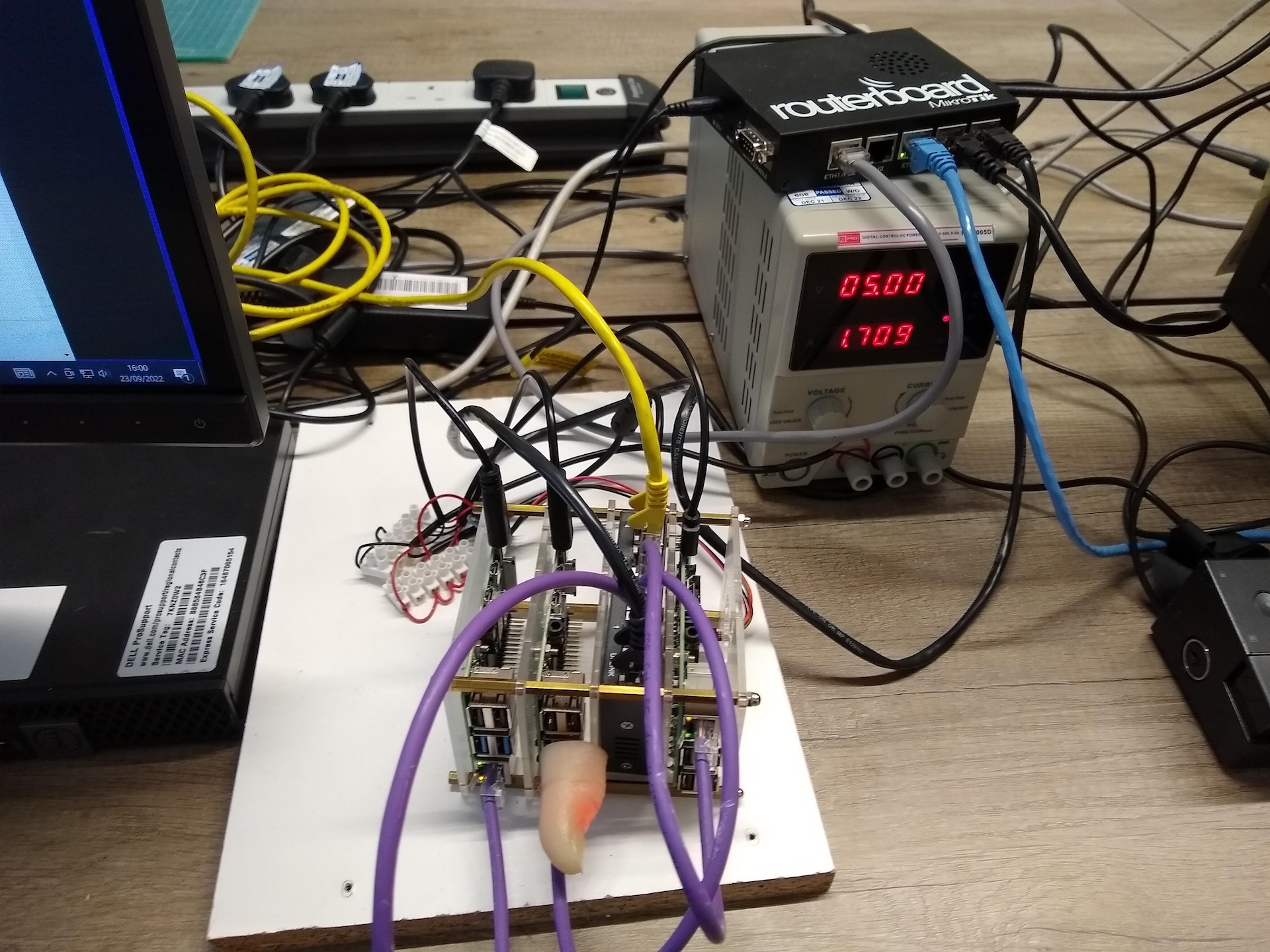
Followers of this blog will know that I have an interest in the whole ecosystem of Raspberry Pi "compatible" boards. By now I have quite a selection.
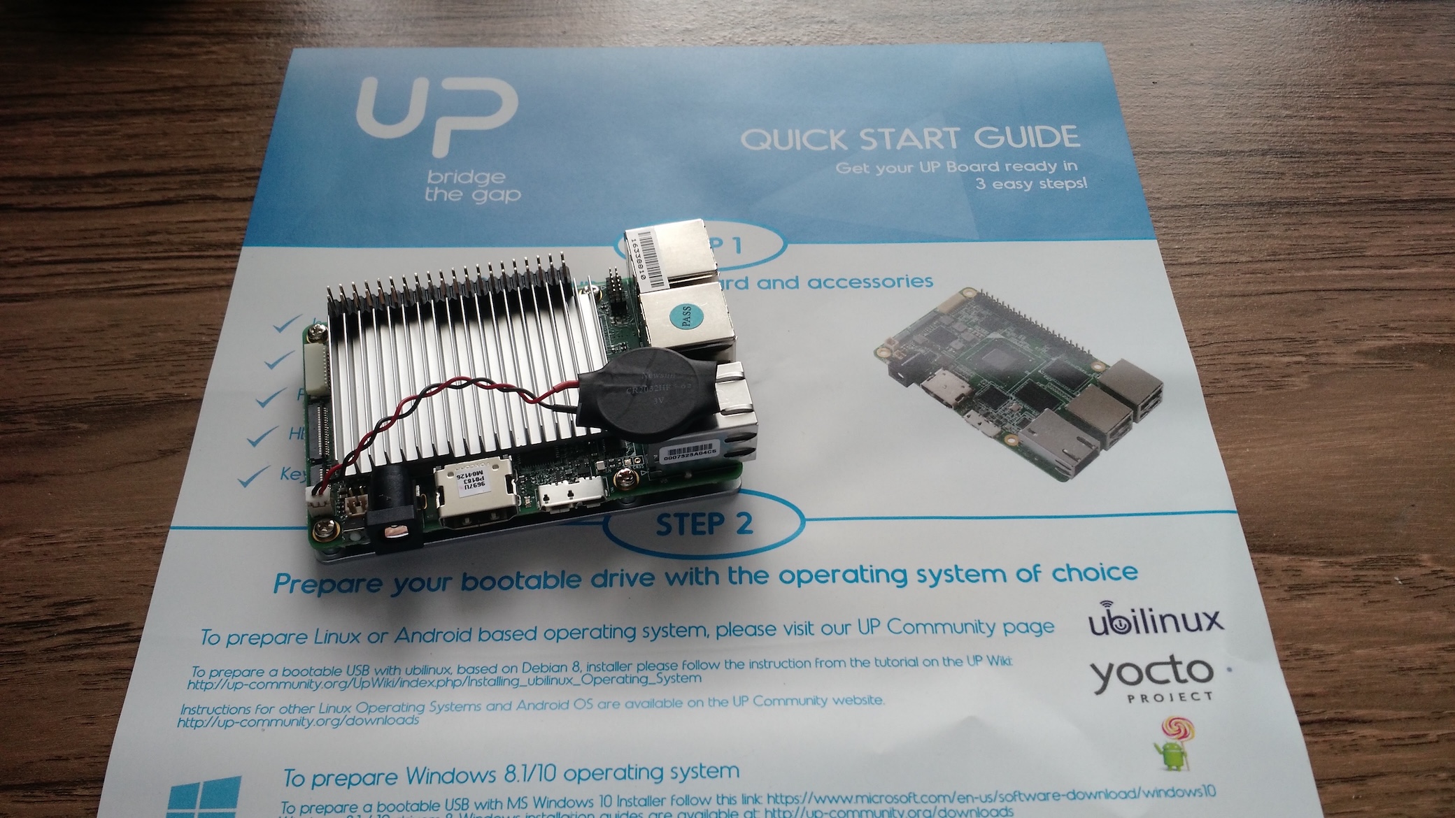
Mostly, the boards I have in my collection are ARM-based, often using a System-on-Chip (SOC) from AllWinner rather than the Broadcom devices used by the official Raspberry Pi boards, but occasionally something a bit different is produced. Last October, I backed the Up board on Kickstarter. There is always a risk (and usually a delay) with crowd-sourcing, so I was hardly surprised when the expected delivery date slipped from Jan/Feb 2016. Today, however, my UP board arrived!
I have been enjoying reading a blog by Ken at Sustainable Suburbia recently, and one post in particular sparked me into action. Not because of its main topic (although that is thought-provoking, too) but because of the mention of an odd early programming language named "BURP" (Basic Using Reverse Polish).
Sufficiently intrigued by this idea, I read around a bit, and decided that I would have a go at producing a version of this. There's not a wide range of information about the BURP language or system, but there are a few articles from 'Wireless World' magazine in the late 1970s and early 1980s which describe the design of both the BURP language and the "Psi-Comp 80" home computer which used it. The key to the system seems to be the National Semiconductor MM57109 "Number-Oriented Processor" which did most of the mathematical work, alongside a more familiar Zilog Z80, so I have started by getting to grips with this quirky co-processor.
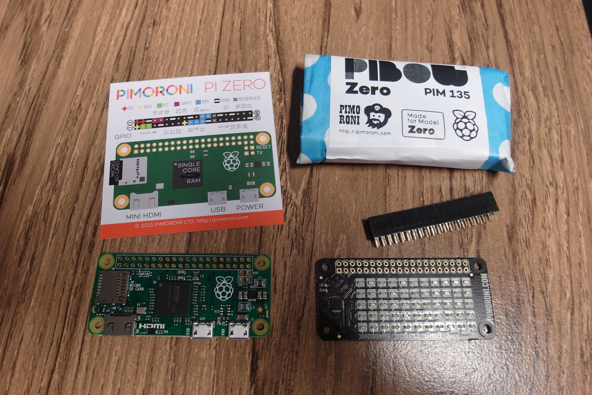
As you might imagine, if you have read many of these posts, I was very excited to hear of the launch of the Raspberry Pi Zero, and ordered one straight away. It arrived this morning, so I am now the proud owner of a Zero, and also a case and the first 'pHat' from the lovely people at Pimoroni
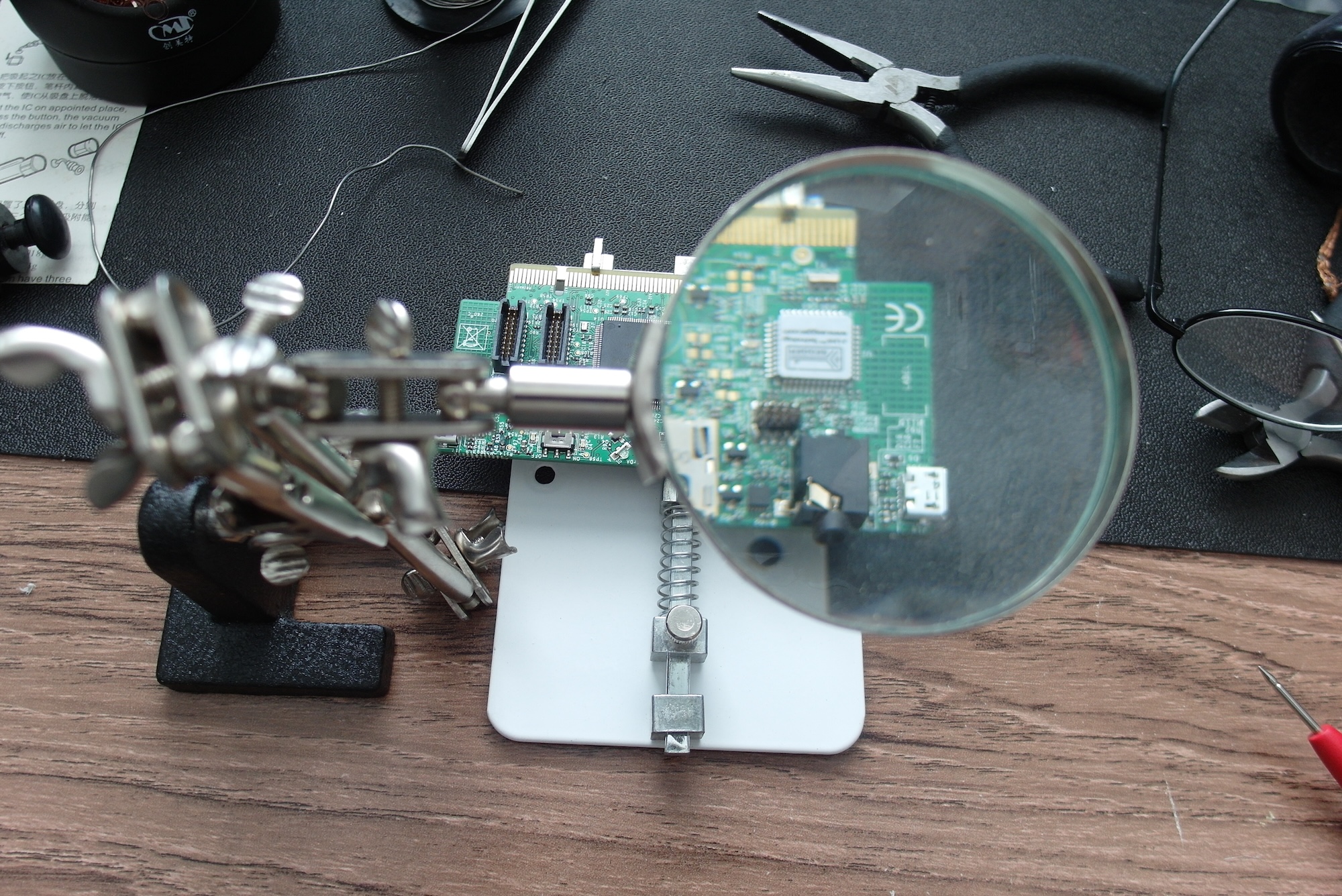
My previous post ended with me waiting for delivery of a surface-mount SWD connector so I could turn a Freescale Kinetis KwikStik K40 into a Segger J-Link compatible debug probe. I placed an order with Farnell UK for an appropriate connector, and it arrived the next day.

Soldering the connector was surprisingly difficult. I had assumed that it would be about as hard as the NXP LPC812 and Freescale KE04 chips which I had recently soldered onto adapter boards, but it turned out to be much more tricky. I think there were several contributing factors. The most obvious factor was the location of the connector, tucked in between an audio connector and the Segger chip. Although some of the pins had clear access for a soldering iron, that was certainly not true for all of them. There was also the matter of my soldering iron and its tip. I have been using the same Antex iron on and off since the 1980s, most of that time with the same tip. It has served me very well for through-hole soldering, wire tinning and so on, but I have now come to the conclusion that the tip is just too large for delicate work such as this.
Although I had some success with using the Segger firmware on a Freescale FRDM board to program a KE04 microcontroller on a header board recently, I was very aware that I was being naughty. The terms of use for the Segger firmware make it clear that it is only for programming and debugging genuine Freescale FRDM development boards, and should not be used for custom hardware. I don't like to break such terms, and the Segger folks deserve to be rewarded for the effort they put into making such useful tools. So I have ordered a real Segger™ J-Link™ and hope to have a lot of fun with it. In the meanwhile, though...
If you have read my previous post in this series, you'll know that I had mixed feelings about the LPC810 and LPC812 chips from NXP. They are certainly simple and flexible in use, but without a stable and predictable technique to program them I just ended up more frustrated. However, I impressed myself by successfully soldering the surface-mount TSSOP package of the LPC812.
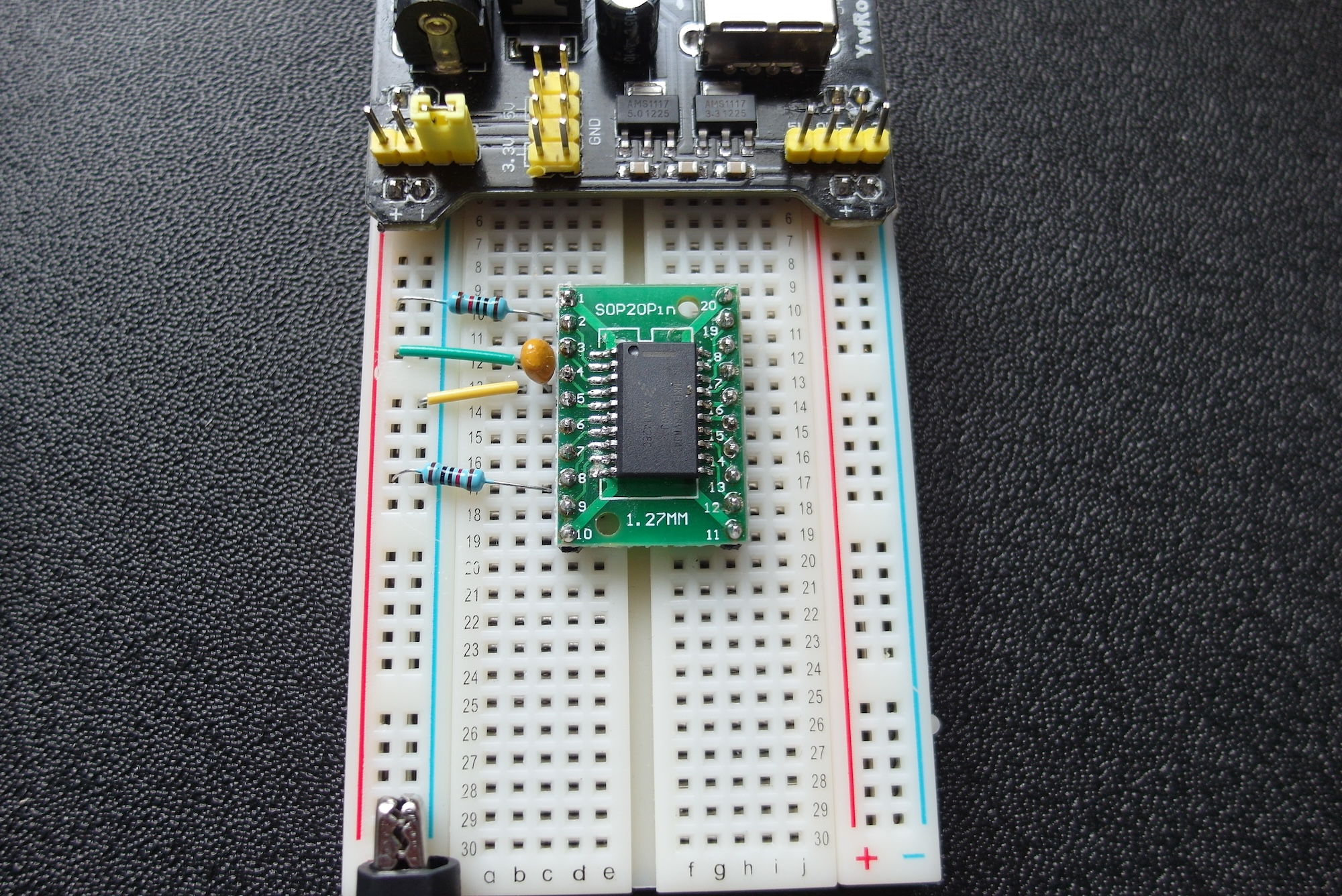
So this time I am attempting to scratch-build a circuit based on a Cortex-M0+ from completely different manufacturer, the Freescale Kinetis KE04. Unlike the NXP parts, this chip has no built-in bootloader, but relies on the "industry-standard" SWD protocol for programming and debugging. Freescale have a huge range of Cortex-M microcontrollers, but the reason I chose this particular one is that it comes in a similar package to the LPC812. I know I can solder this, and I already have a breadboard adapter to fit it.
As I mentioned in my previous post in this series, I have been planning for a long time to make my own ARM Cortex development board from scratch. After a lot of mulling around, and a bit of a false start with the LPC1114 chip, I discovered JeeLabs, a comprehensive web site, blog and upcoming book all about this sort of stuff run by Jean-Claude Wippler. A lot of the older material is based around Atmel AVR chips. Starting in November last year, however, Jean-Claude has been exploring the world of 32-bit ARM, beginning with the cute little LPC810, in a breadboard-friendly eight-pin Dual-in-Line package.
As many of my readers will be aware, I have quite an extensive collection of microcontroller development boards with a wide range of controller chips from a variety of architectures and manufacturers. While it's fair to say that I enjoy programming and creating projects with these boards, there has always been a niggle in the back of my mind that too much of the work has been done for me. Often it's even worse than that: chip manufacturers delight in cramming boards full of peripherals and options which are great to play with but not much help in learning about the needs of the basic hardware.