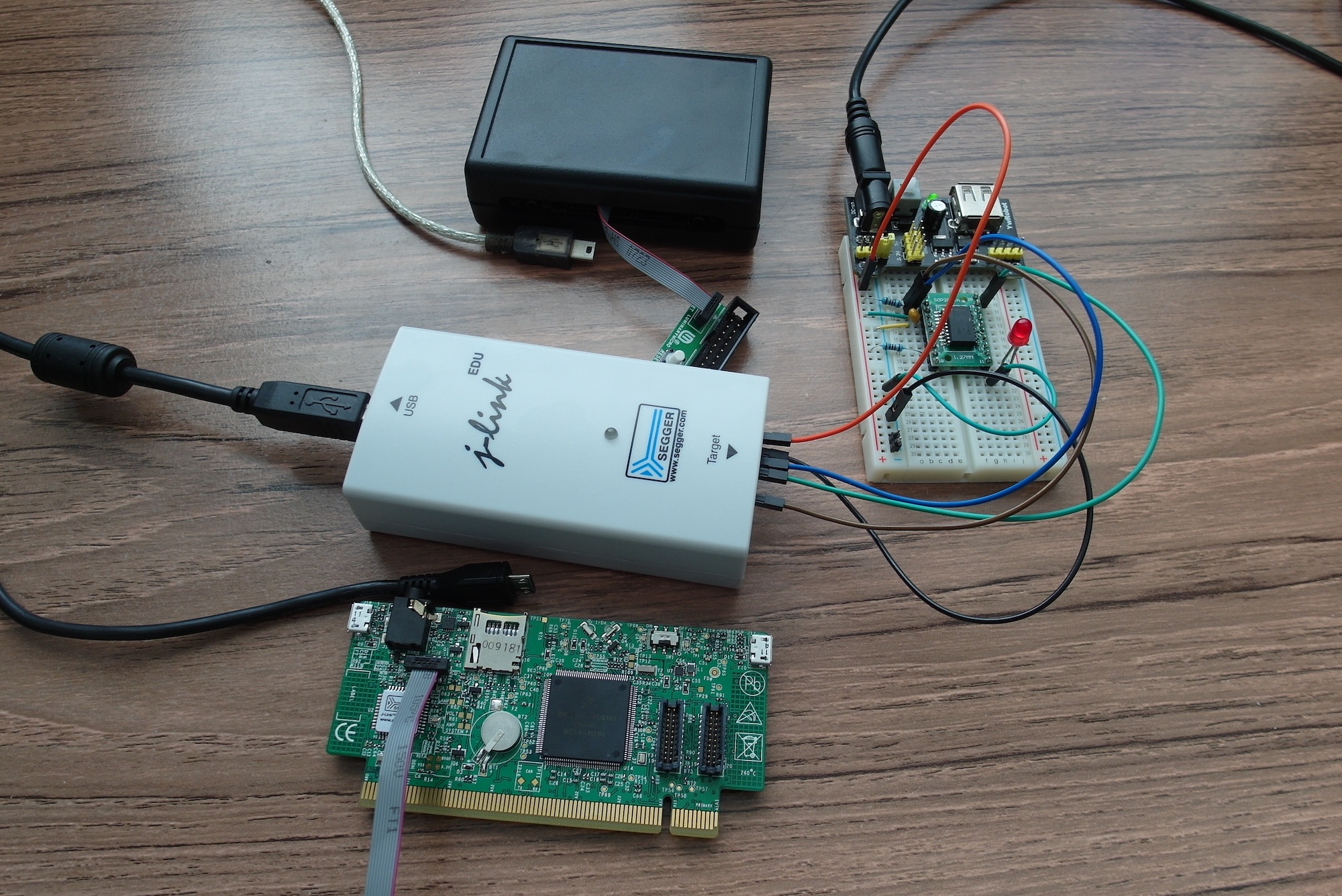
My previous post ended with me waiting for delivery of a surface-mount SWD connector so I could turn a Freescale Kinetis KwikStik K40 into a Segger J-Link compatible debug probe. I placed an order with Farnell UK for an appropriate connector, and it arrived the next day.
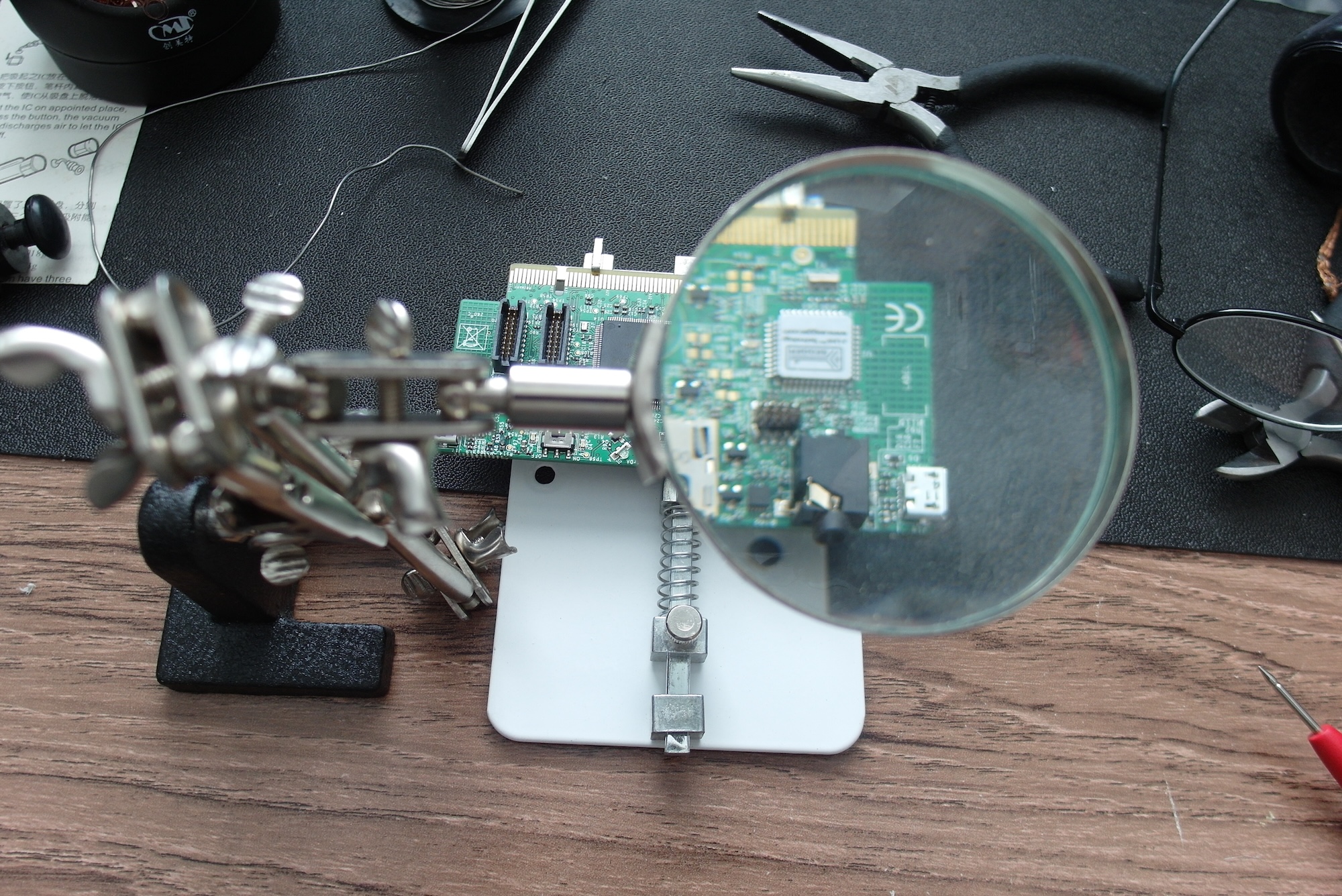
Finally, of course, there is my own skill level and experience. This task was plagued by solder bridges between pins and required lots of continuity beeping and solder-wicking to get things clean.
- Top tip: two of the pins on the 10-pin SWD connector, which happen to be adjacent, are both connected to ground. However much solder you wick, you'll never get them isolated. Sigh.
After reading up, it seems that I might have had better luck had I spread on some extra flux, rather than just relying on the flux core in the solder.
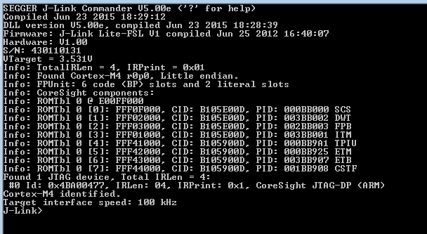
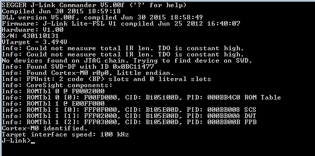
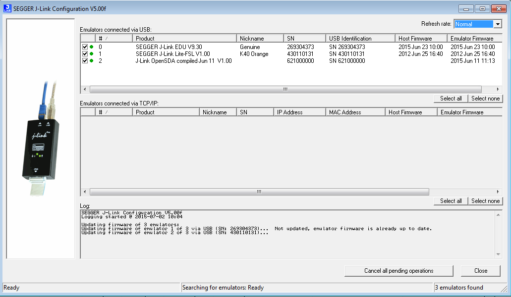
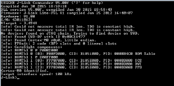
In particular, two useful programs are J-Link Commander and J-Link Configurator. J-Link Commander is a command-line tool which looks for a Segger J-Link debug probe attached either by USB or ethernet. If it finds one it displays some information and waits for textual commands to control it. J-Link Configurator tries a bit harder, and will find multiple probes if more than one are attached. Any J-Link devices it finds are listed, along with driver and firmware version numbers and, where possible, the option to update software. The combination of these two tools eventually enabled me to get the KwikStik working as a debug probe. I tried a lot of things, but I'm pretty sure the following things did need doing:
- Remove all other J-Link compatible devices before starting. Although these tools should work with multiple debug probes, I had a lot more problems with more than one attached.
- Attach the probe and wait for any driver installation to complete before starting either of the J-Link tools. (I seemed to have better luck when I attached the device to a different USB port which had not been used by another J-Link.)
- Check that the target switch on the KwikStick is in the correct position, and pay attention to the output from J-Link Commander. If the switch is in the wrong position, the description of the target device will list a Cortex M4, rather than the actual target device (in my case a Cortex M0+ which reports as Cortex M0). If it shows the wrong target, power off the target and the KwikStik, unplug the USB, switch the switch, re-plug and re-start.

- Depending on what versions you have, you are likely to need to update the KwikStik firmware. This is a simple process using J-Link Configurator, and only took a few minutes. Once done, power off and unplug everything, then start again.
With any luck, this set of steps, in some order, should help you get a working KwikStik Segger J-Link Lite debug probe, licensed for use with all Freescale ARM chips.
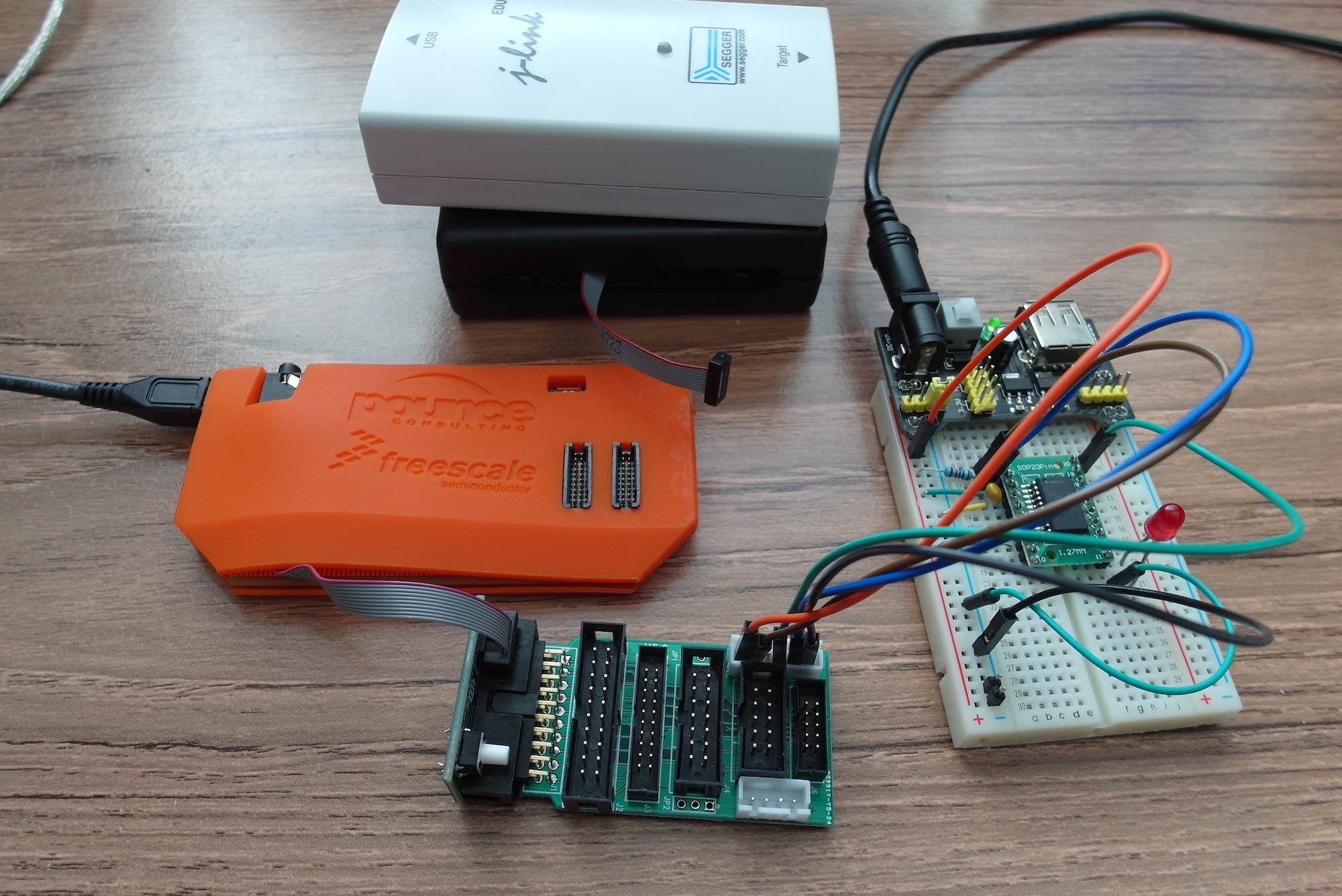
As a twist to the story, I was determined to get this working, but I did have a fall-back position. In the same delivery from Farnell, I also got a Segger J-Link EDU". As pointed out by Erich in the comments to my previous post, this is reasonably priced, and licensed for use in educational and non-profit situations. That works for me. In the unlikely event that I ever end up making any money from this blog, I'll be more than happy to rush out and buy the full commercial license. In the meanwhile, I now have three kinds of Segger, each with different capabilities and licence terms.