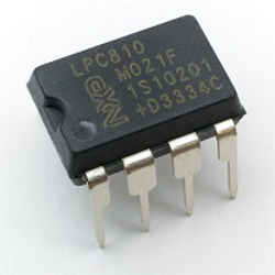
As I mentioned in my previous post in this series, I have been planning for a long time to make my own ARM Cortex development board from scratch. After a lot of mulling around, and a bit of a false start with the LPC1114 chip, I discovered JeeLabs, a comprehensive web site, blog and upcoming book all about this sort of stuff run by Jean-Claude Wippler. A lot of the older material is based around Atmel AVR chips. Starting in November last year, however, Jean-Claude has been exploring the world of 32-bit ARM, beginning with the cute little LPC810, in a breadboard-friendly eight-pin Dual-in-Line package.
Although the point of this exercise is to build my own development boards, sometimes its comforting to have something to fall back on to test things out. NXP originally produced a nice simple development board for this chip, but sadly it seems that this board is no longer available, so if I am to do anything with this device I will have to make my own.
The first step is to find out a minimum circuit. Luckily, JeeLabs has this covered. There are some interesting things about this circuit. The first is the very small number of components There's the microcontroller itself, a smoothing capacitor for the power pins and an LED. The second interesting thing is the LED. It is mainly used as a rough and ready regulator to drop 5V, provided by a serial adapter board, to 3.3V for the device. For a purely 3.3V circuit, even that would not be necessary! The simplicity of this circuit made me very happy. Surely even I can't get this wrong! I still have niggling worries about the lack of any pull-up or pull-down resistors on any of the communication pins, but Jean-Claude has obviously made it work. I quickly assembled the specified circuit on a small breadboard, following the JeeLabs instructions.
(Sadly, since writing this article, the Jeelabs website has gone away)
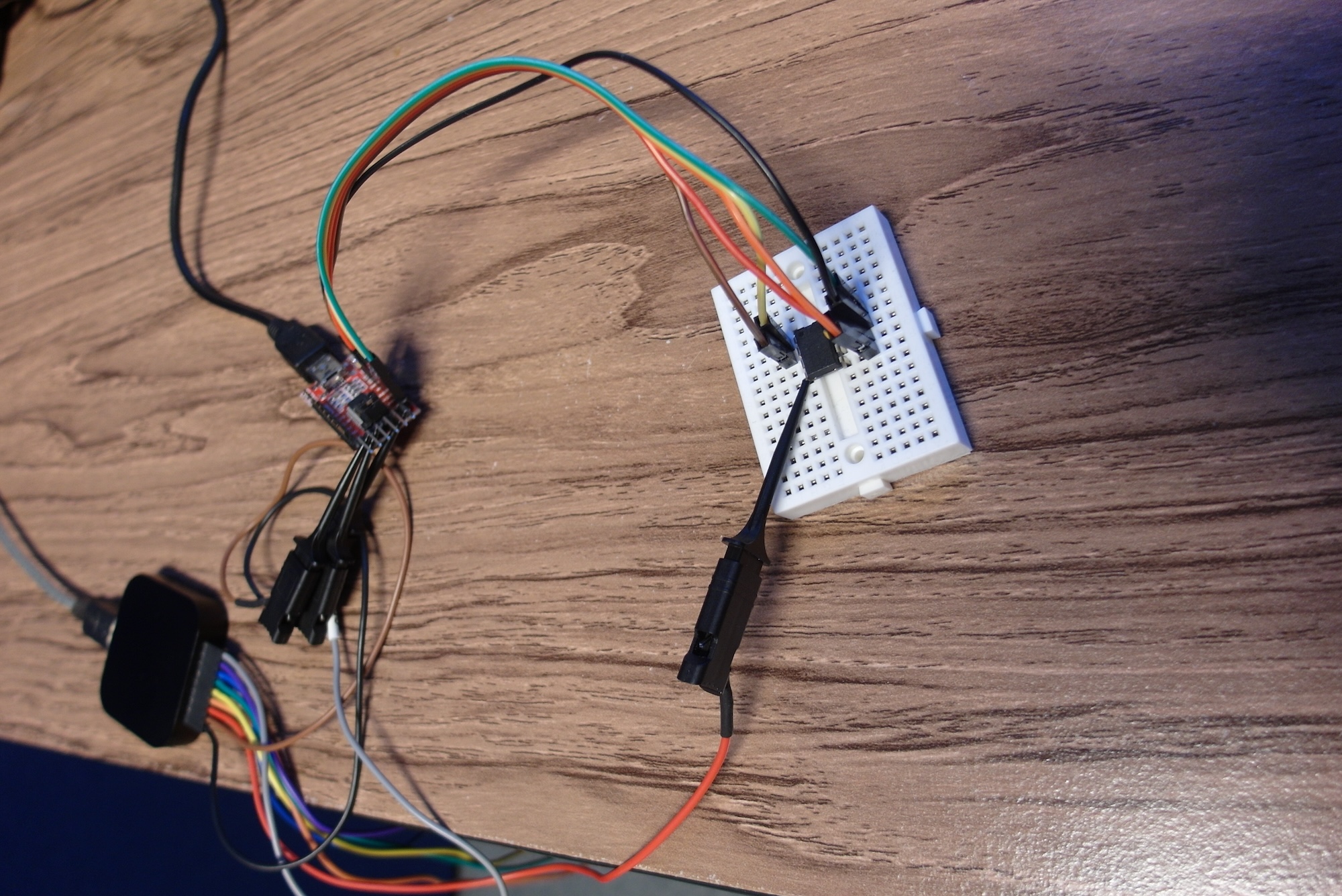
If The ISP pin (pin 5) is low when the chip powers up or comes out of reset, it will enter programming mode and expect commands and data over a serial port on pins 2 and 8. While serial port adapters are cheap and plentiful (even though they don't often have an output which does exactly the right thing for the ISP pin) this approach does mean that some special software is needed which speaks the correct protocol over the serial port. JeeLabs recommends some software called lpc21isp which it recommends installing in a Linux virtual machine. I tried this approach and spent several days messing with software and modified serial adapter boards. All with no success.
In my case it seems that code in a Linux VM was either unable to write to the USB serial port, or suffered timing problems which prevented it form working. Whatever versions I could find for Windows were not quite the same and didn't work either. Eventually I gave up on the modified serial board approach, and fitted a manual ISP button (initially it was just a jumper cable). This allowed me to, eventually, get some JeeLabs example code onto the chip so I could see it blink an LED. The process still seemed pretty hit or miss, though. A large proportion of the time the software download would fail, with no obvious reason why, and messing with a manual ISP switch became very tedious. I also faced the problem that I was not set up to develop code in the same way as Jean-Claude at JeeLabs, so I was mostly limited to the supplied examples. I even tried connecting my Keil ULink 2 debug proble to the SWD pins, in an attempt to use Keil uVision to write code for this chip. Again without success. Adafruit recommends the LPCXpresso IDE, so I also installed that. Although I could use it to program other NXP chips on pre-made development boards, I still had no real success with programming the LPC810.
Next time I'll step into the confusing world of SWD, but this time I'll try with a microcontroller where I am already comfortable with the development software.