As many of my readers will be aware, I have quite an extensive collection of microcontroller development boards with a wide range of controller chips from a variety of architectures and manufacturers. While it's fair to say that I enjoy programming and creating projects with these boards, there has always been a niggle in the back of my mind that too much of the work has been done for me. Often it's even worse than that: chip manufacturers delight in cramming boards full of peripherals and options which are great to play with but not much help in learning about the needs of the basic hardware.
Unlike the simpler world of Arduino, there are a multitude of choices when it comes to Cortex-M. ARM itself just sells core designs, it does not make chips - that is left to third parties: anyone who can pay the licence fees to ARM and has the resources to produce and market the silicon. Naturally these manufactures do not all make exactly the same devices. To start with, ARM provides a range of core designs in the Cortex-M series including M0, M0+, M3, M4, M4F and M7. Although broadly compatible, these chips offer different base capabilities. Each manufacturer chooses one or more of these cores and adds their own on-chip circuitry such as UART, SPI and I2C, analogue input and output, timers and so on. Some manufacturers (for example Cypress, in their PSoC range) add all sorts of programmable logic and analogue components, while others stick to simpler, cheaper designs. Each manufacturer also makes choices about power consumption and the ability to "switch off" parts of the chip to consume less.
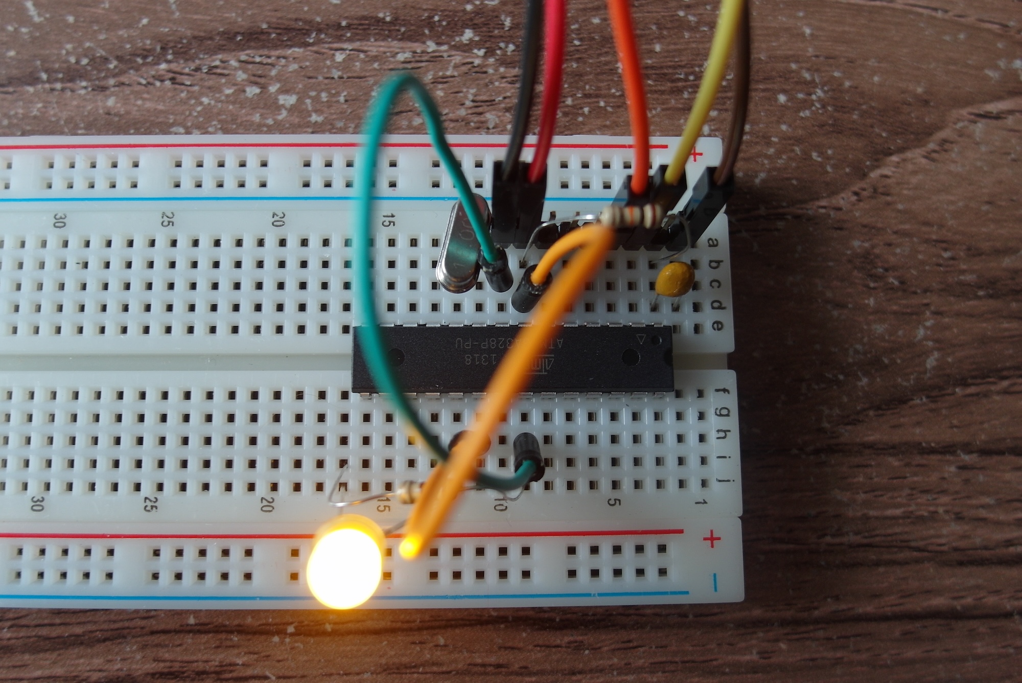
For me, the biggest problem has been finding out what the minimum circuit for a given chip might be. I view this as the electronics equivalent of 'Hello World' or 'blink' in the software world. When starting out there are far too may choices to make. As well as which controller chip, there's how to wire it up to power and stuff, pull ups and pull-down resistors, capacitors and crystals, how to connect it to some sort of programmer, which programmer to use, which development software to use, and what to write to exercise the system. I always prefer to learn by starting with a bare minimum working design and making and testing small changes until I get to where I want. In the embedded design world this does not seem a very common approach. Instead, we are presented with huge technical references and datasheets, with no worked examples, which just reveal even more options to get wrong.
What I really want is a guaranteed minimal circuit to start with, so that if the device won't start or won't program, I know the problem is elsewhere. My naive assumption was that each manufacturer would obviously produce an 'application note' with such a minimal circuit, but no. I may be looking in the wrong place, but so far I have not found such a document from any manufacturer. I even bought some 'embedded system design' books in the hope that they might help, but they all start with software, and just assume that all the electronics is already in place.
With no apparent support from the manufacturers, I am left looking to the web for help. To try and eliminate PCB design from the problem, I plan to start with one of the few DIP ARM chips, and see how far that will get me.
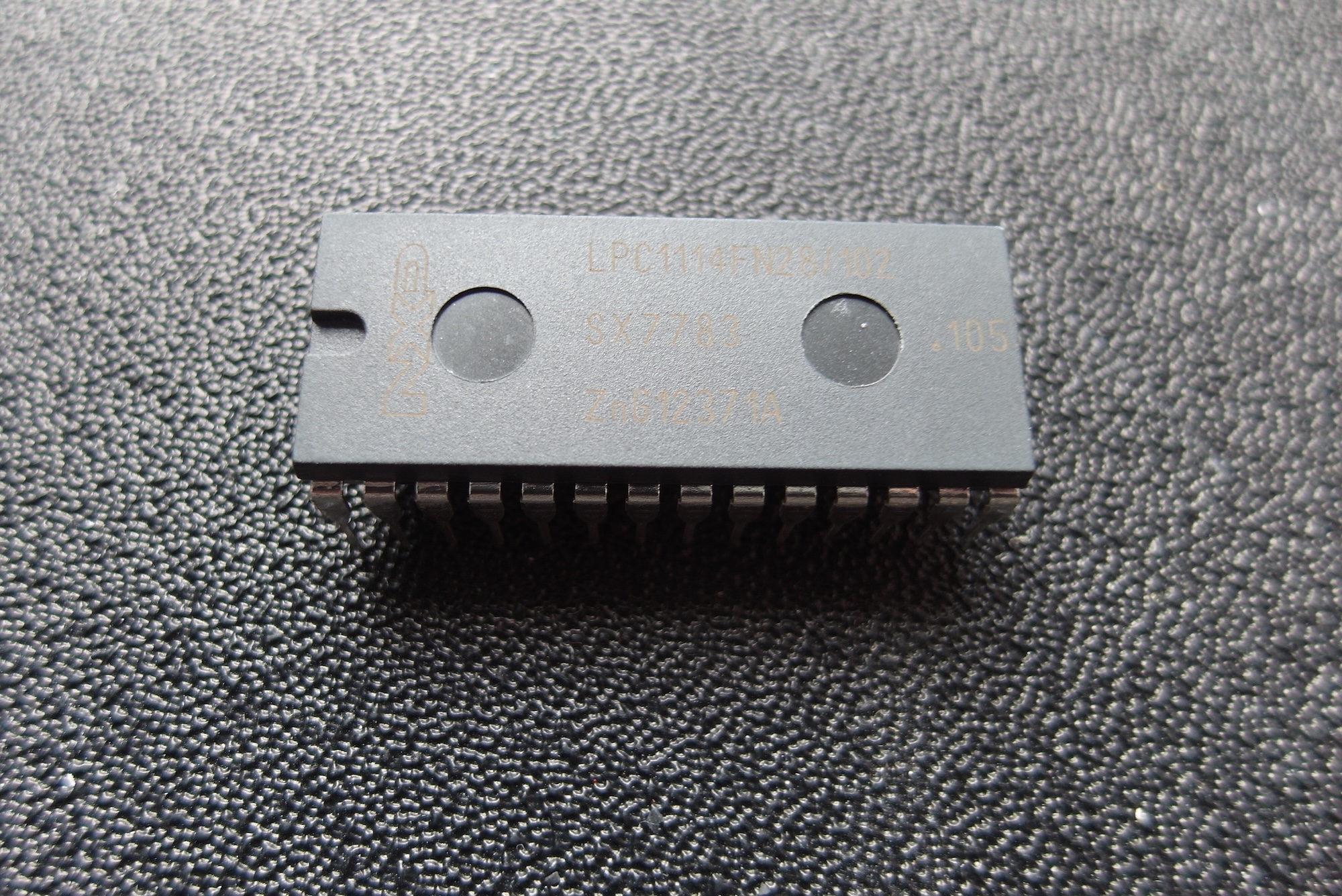
I eventually managed to get hold of one for a mostly reasonable price, but so far I have not yet dared to try and program it in case I kill it!
It took me several months of indecision before I finally discovered some very helpful resources about another NXP chip, the LPC810. This is a much smaller DIP package with only 8 pins, not enough for even a basic JTAG connector, so it uses its own bootloader firmware. Next time, I'll cover my adventures with LPC810, and its close cousin LPC812.