So I’m still banging my head against the difficulty of making a simple serial connection between my Raspberry Pi and an ATMega chip on a daughter board. And I still have not got it working properly.
Overnight it occurred to me that I ought to have turned off the serial port login on the Raspberry Pi. I’m sure this was getting in the way and confusing things, so I followed some steps I found from a quick Google search.
Next, I have begun to distrust my soldering, and continually messing with the serial wiring is not doing the rest of the joints much good, so it was back to a breadboard to try and work out what was going on. I quickly built the circuit from last time, and tested it by running the Arduino GUI on the Pi and re-burning my test program: a version of the ASCII table example which repeatedly generates the table, waits for half a second then does it all again. This time I have also added a new feature. I switch on “Pin 13” when I am sending data, and switch it off while waiting, so that I can visually confirm that the program is running just by attaching a LED.
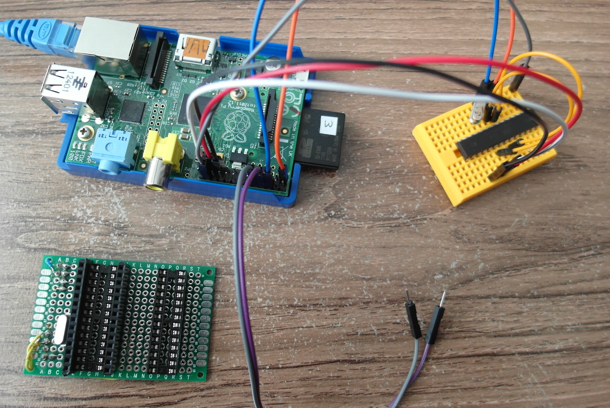
With the Pi and Duino connected, at least enough to report a success in programming, I attached the LED and saw it happily flashing away. Good!
Now time to try the terminal. I started Microcom on the Raspberry Pi using sudo microcom -p /dev/ttyAMA0 -s 9600
and at last saw something. Not useful characters, mind, but something. It seems there is a problem with the baud rate of the text.
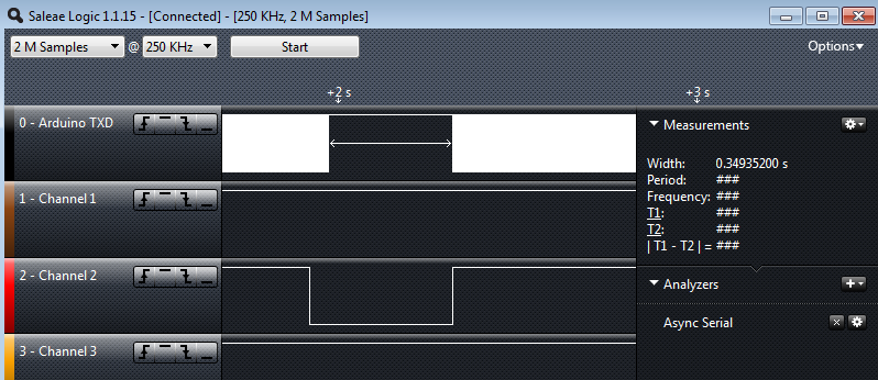
I tried a few other baud rate settings, but with no extra clarity. I then plugged in my Saleae Logic, and set it to “auto baud rate”. It had a think, then showed that it had found valid characters at a baud rate of 13157 baud. This is a very weird speed, and nothing like the 9600 baud the code claims it is using. This made me think, so I also measured the supposedly 500ms wait between characters and saw that it measures as roughly 350ms, a long way off from what I would expect.
This hints to me that there is something wrong either with the crystal clock or with the way the AVR has been set up to expect a different clock frequency. While writing this it suddenly occurred to me that maybe my “boards.txt” setting was wrong. I guess the Gertboard uses a 12MHz crystal or something, because when I looked back at my settings, there it was:
gert328.build.f_cpu=12000000L
The MCU is set to think it has only a 12MHz clock, when it actually has a 16MHz crystal. That’ll teach me for blindly copying someone else’s config file :(
Now I just need to put everything on my proto-board back where it should be, and see if I can finally get serial communication to work.
Great series of posts on this, it has spured me on to order some bits and have a go myself. Brings back memories of trying to get a pic to talk, you make this all looks a lot more simpler…other than your 12/16 MHz mix up. As the pi doesn’t have too much spare 3.3v power is it better to level shift the data lines or power (voltage reg to 3.3v) to the 5v rail for incorporating into projects?
Thanks for the kind words.
I made a concious decision when I started this blog that I would not clean up or glamorize things, but instead write what happens, mistakes and all. And this little project certainly seems to have had more mistakes than some of my others!
As for power and level shifting, the research I have done seems to indicate that the ATMega chips are pretty tolerant and will work happily with anything from about 3V upwards. My current plan is to see how far I can go with 3.3V from the Pi for both Vcc and data. If that does end up causing problems, I might try 5V Vcc and 3.3V data, which many people report seems to work. Although I did buy some little level shifters several months ago, I’d prefer not to use them if I don’t have to, as I really want to keep the circuit as simple as possible.
If I find I want to drive anything from the AVR with higher current needs, I’ll look into buffers or drivers at that point. For now I’m mainly seeing how far I can push such a simple circuit.