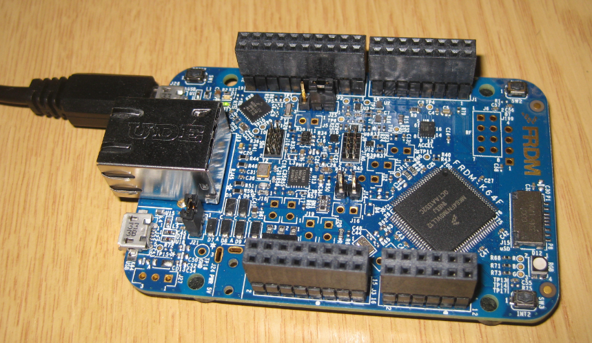
Today, I thought I'd have a go at running one of the simple demonstrations I saw at the recent Freescale Tech Day in Milton Keynes. I have a FRDM-K64F development board which I bought a few weeks ago, and my fresh installation of the KDS IDE. The K64F is a lovely board with a powerful ARM Cortex M4F CPU running at up to 120MHz, has built-in ethernet and debugger support, and was used for several of the demonstrations, so it seems a reasonable choice. Getting started is a lot more tricky than with an Arduino, though.
Here's what I did, mostly following the script of the demonstration to get me started.
Replace the mbed bootloader with one more suited to debugging a C program
- Download the Segger J-Link firmware from a link at the bottom of http://www.segger.com/opensda.html
- Install the J-Link firmware as described in http://mcuoneclipse.com/2014/04/27/segger-j-link-firmware-for-opensdav2/
Create a project in KDS
- Open KDS, dismiss the welcome screen if you see it, then right click in the "project explorer" panel on the left. Select New Project and choose "Kinetis Design Studio Project"
- Name the project, e.g. K64F-example
- Select MK64FN1M0xx12 as the processor type
- Deselect 'Use Kinetis SDK'
- Select 'Processor Expert'
- Click Finish
- If you do not see any extra panels, choose "Show Views" from the "Processor Expert" menu
Add a Processor Expert component
- Go to the Components Library tab/li>
- Switch to Alphabetical View
- Find BitIO and drag it to the Components folder in the Components view
- Right Click on BitIO component and select Inspector
- It should show a red box indicating a missing value for the pin to use
- Select "advanced mode" from the bar above the inspector window
- Give the pin a name (eg. LED)
- Click in the top red box and start typing, watch as the big list of pins is filtered. Enter PTB22
- Set "Direction" to output and "Initial value" to 1
- In the "Project Explorer" panel expand your new project if it is not already, then right-click ProcessorExpert.pe and select "Generate Processor Expert Code"
- Now expand Sources and open "main.c"
- Look for the bit where you are supposed to "write your code here" and insert:
for(;;) {
  LED_ClrVal();
  LED_SetVal();
}
- save the file and click the "hammer" icon to build the project
Run the new program using the debugger
- Set up the project to use the J-Link debugger: click the little triangle next to the beetle icon on the top bar and select "debug configurations"
- Double-click GDB SEGGER J-Link Debugging
- The annoying bit: open the "Debugger" tab and enter "MK64FN1M0xxx12" in the device name and click apply
- Open the "Startup" tab and un-check the "ENable SWO" box
- Click "debug" at the bottom of this pop-up window
- If all goes well it will switch to the "debug" perspective. If it asks permission, feel free to check the little box so it does not ask next time
- If you see a "terms of use" message from Segger, accept it
- By default the debugger will have placed a breakpoint at the start of "main". Double-click in the left margin next to the two LED lines to set two more
- Now you can click the green "play forward" arrow in the top bar to advance to the next breakpoint
- Press "play forward" several times and watch in amazement as the red LED on the board toggles on and off
That feels like quite a slog, but by this point we have made sure that the IDE is working OK, and is configured for the correct board, installed and tested the Segger J-Link debugger firmware on the board, and used Processor Expert to implement a (manual) blinking LED. This is a great jumping-off point for future projects. If you follow these steps, I recommend saving the project in your favourite version control system, so you can come reliably back to here later.