Yesterday I wrote about how I managed to get an "Arduino" (or at least the AVR ATMega328 chip which powers one) attached to and programmed by my Raspberry Pi. However exciting a blinking LED may be, though, it's not much use if the only way to change its behaviour is to completely re-program the chip. After playing with this for a while I decided that I need a way to talk from the Pi to a running program on the AVR. The obvious way to do this is using a serial port ("UART"). Both the Raspberry Pi and the ATMega328 have built-in serial UART support, so it seemed reasonable to connect the two together and see if I could get them talking.
As an aside, there is strictly already a serial connection between the two devices. the SPI connection used for programming the AVR uses just one input and one output wire, so it counts as a serial connection. Arguably I could use this to communicate with a running program. As it turns out, this is actually a bit more complex. SPI requires one end of the connection to be a "master" and the other a "slave". It is the master's responsibility to provide the clock and initiate all communication (often by controlling an "enable" line to indicate which "slave" device it is talking to). Normally both the Raspberry Pi and the AVR want to be "master". The SPI protocol is also synchronous, in that data coming in is clocked at the same time as data going out. These things make it generally a lot more tricky than a simple UART. I may try using SPI to talk to the AVR later, but for now I'll go with the UART.
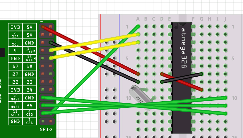
UART connections have no master and slave roles, each end is conceptually identical to the other, having both a transmit (TXD) and receive (RXD) pin. For a UART connection to work, the TXD from one end must be connected the RXD of the other, and vice versa. I wired the TXD from the Raspberry Pi to the RXD of the AVR, then the TXD of the AVR to the RXD of the Raspberry Pi. This is where it all seemed to go wrong.
I had programmed the AVR chip with a version of the "ASCII table" serial port example from the Arduino IDE, and I was hoping that by connecting a terminal emulator on the Raspberry Pi (I chose microcom, as recommended in the comments to a previous article") I would see the output on the Raspberry Pi console.
I didn't.
So I pulled out my Saleae logic analyser and looked at the pins. It seemed that, somehow, both ends were transmitting on the same pin, and confusing each other. So I swapped the wires over, tried again, and now it seems that both are transmitting on the other pin. I'm somewhat baffled, but I have run out of time, so I'll have another go another day.