A few days ago I wrote about a "learning timer" that I had built using an Arduino Uno. Arduino boards are pretty easy to come by, and also easy to work with, but can be a bit expensive to build in to things (a genuine Arduino Uno from the manufacturer will set you back 20 Euros, for example) Once I had got my circuit and software working on the real Arduino, the next step was to see how cheap and simple a circuit I could make that would also work.
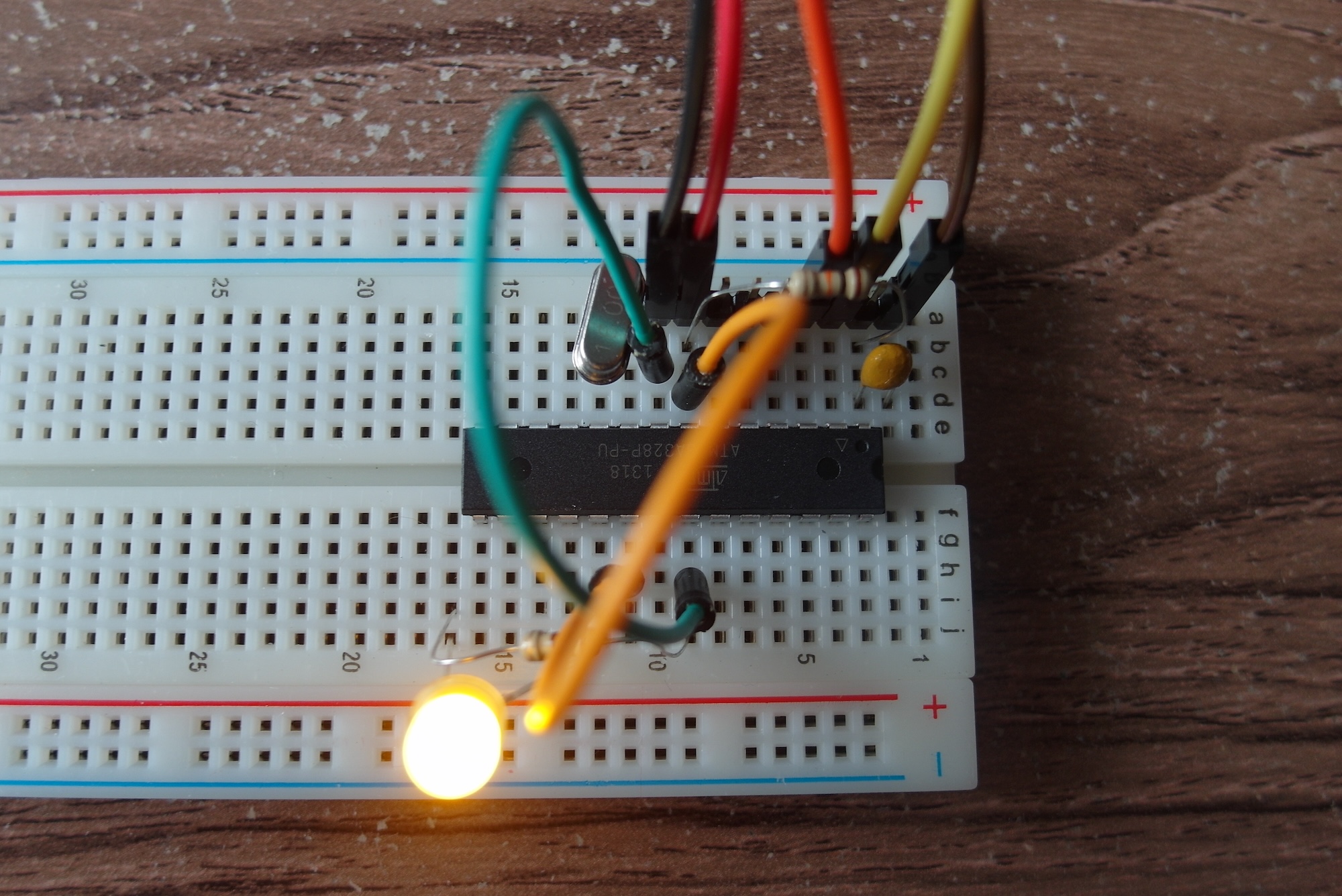
Luckily, some excellent hackers in Morecambe have already done the basics, in a circuit called the shrimp. At its most minimal, this is just an AVR microcontroller, a crystal, a capacitor, a resistor, and a couple of wires. They also have a variety of (slightly) more complex designs which are better at various aspects, but for now, this should be enough for me.
The shrimp tutorial recommends a CP2102 USB/UART module for programming, and I knew that I had a few of this sort of thing lying around. It turned out that the Arduino is a 5V system, and all the USB serial boards I have are 3.3V ones for use with Raspberry Pi. I crossed my fingers and plugged it in anyway. However, when I came to try and program the board, I got the infamous
avrdude: stk500_getsync(): not in sync: resp=0×00
from the Arduino IDE. This error happens whenever the IDE cannot communicate with the microcontroller, and can be due to many different problems. I went over my wiring very carefully, and did find a mis-placed LED leg, but even after i fixed that, no luck. I even tried adding a 5V power supply to the breadboard to power the chip, but still the same error.
After some more thinking, it finally occurred to me. The microcontroller chips I had ordered were the (slightly cheaper) "raw" version without an Arduino "bootloader". The bootloader is a small program that runs on the microcontroller and is responsible for downloading new application programs. To get past this hurdle I needed a microcontroller with a bootloader. To test my hypothesis I levered the ATmega chip out of an Arduino and plugged it in to my shrimp. To my delight, it worked. Even better, it worked and communicated powered solely by the 3.3V from the serial board.
This was not a permanent solution, though. I had hardly managed a cheaper circuit if I had to cannibalise a working Arduino to build it! I vaguely remembered that I had seen something that looked interesting along these lines, and a bit of searching turned up a clever self-build bootloader programmer at Adafruit called "ArduinoISP".
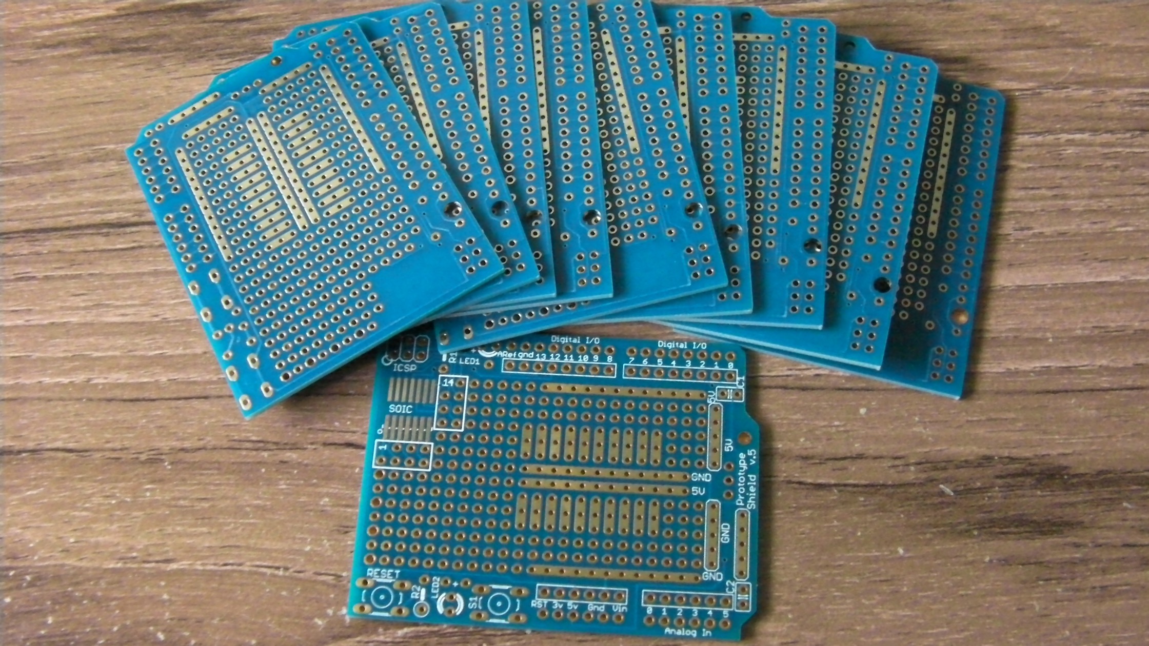
Months ago, while poking around looking for stripboard I found someone selling a ten pack of bare-board Arduino shields for just a few pounds. As luck would have it, these boards were pretty much identical to the one in the Adafruit kit. All I needed was the ZIF socket which I got for about £2.50 from proto-pic. The wiring instructions were straightforward, and the programming software installed and ran on my Uno. Within a few minutes of completing the build, I had a freshly-bootloadered Atmega328 humming away nicely in my breadboard shrimp.
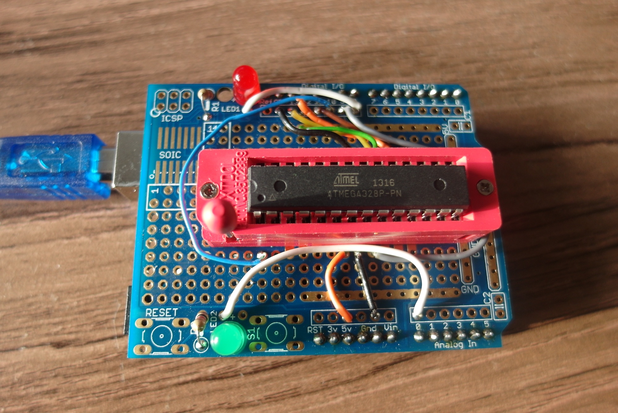

Filled with enthusiasm, I had tp push on and convert the breadboard shrimp to a learning timer. I removed the LED and it's current resistor, and added the "flowing water" LED array, the two buttons and the buzzer. A quick program from the same Arduino sketch that I used on the "real" Arduino Uno and I have a completely self-built learning timer. Here are the two versions for comparison.
The next step is to solder the circuit on some proto-board, add a battery power supply and put it in some sort of enclosure. Then I'll finally have something that anyone can use (if they want to, of course.) For today, though. I'll stop here.