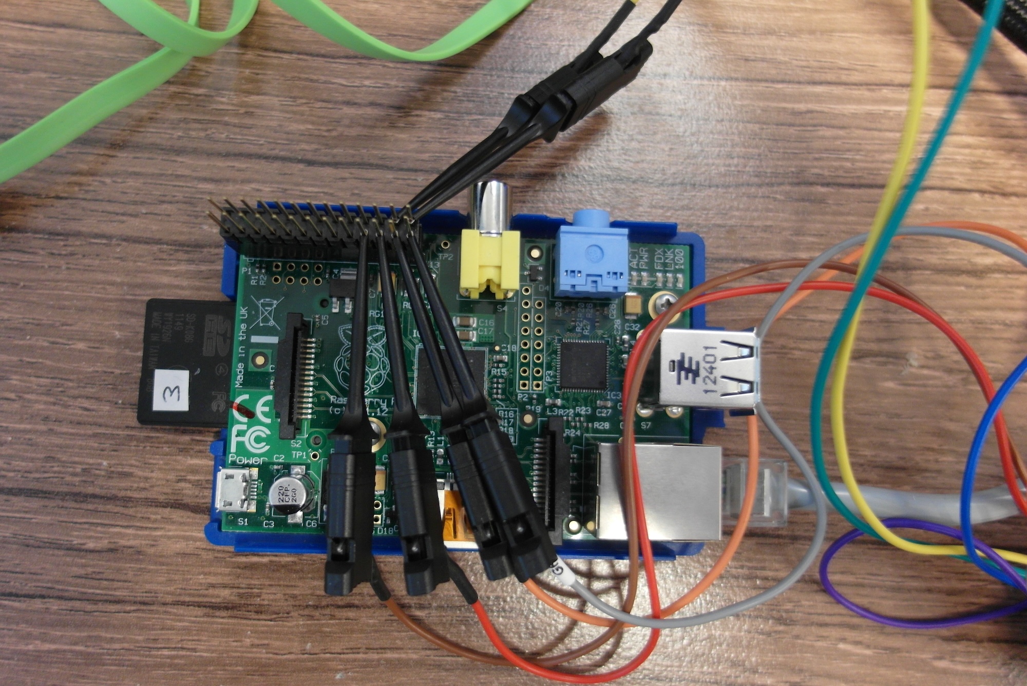
Having wasted all my free time yesterday on trying to find out how the PiFace CAD is interfaced to the Raspberry Pi, I thought I'd take a different approach today. When I was last working with SPI, I used my trusty Saleae Logic analyser to find out what was happening, so I thought I'd connect this up between the Raspberry Pi and the PFCAD, to see what is really going on.
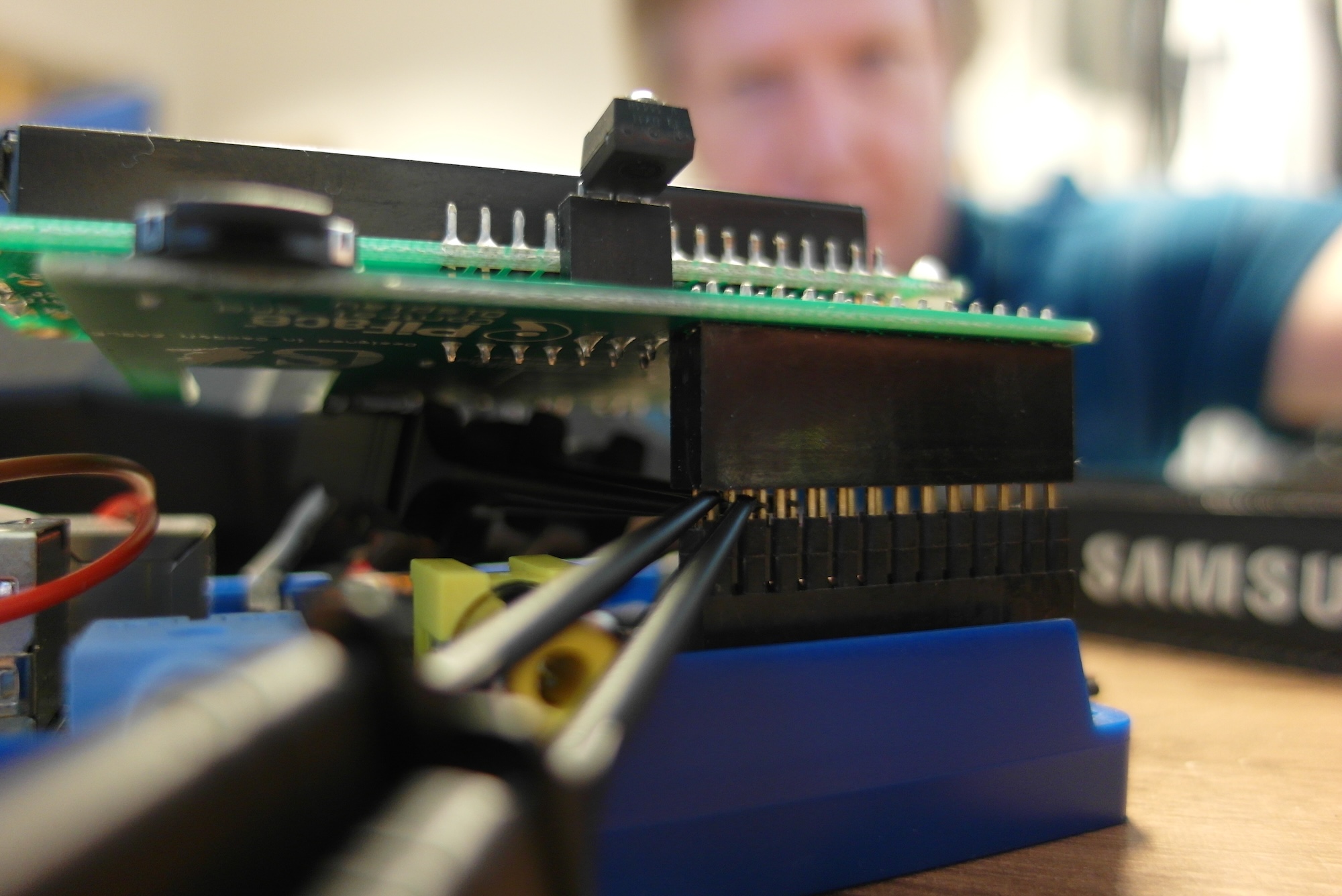
The first problem, as I pointed out in my initial review of the PiFace Control and Display, was that the PFCAD board does not provide easy access to any of the Pi's GPIO pins. I did not want to mess around unsoldering the PFCAD, so my solution was to extend the Pi's GPIO pins with the same kind of "long leg" socket that I use for my own circuit boards.
I then ran the "sysinfo" example, which had worked fine yesterday: python3 /usr/share/doc/python3-pifacecad/examples/sysinfo.py. Oddly, it failed, with a very strange complaint.
Traceback (most recent call last):
  File "/usr/share/doc/python3-pifacecad/examples/sysinfo.py", line 5, in import pifacecad
  File "/usr/lib/python3/dist-packages/pifacecad/__init__.py", line 19, in from pifacecommon.interrupts import (
EOFError: EOF read where not expected
After a bit of poking around, it seems that something has gone wrong with "python3". When I tried the outwardly similar python /usr/share/doc/python3-pifacecad/examples/sysinfo.py it worked without any complaints. I can only assume that this is a result of SD card corruption when the Pi was powered off. Maybe I should use my Pi Supply switch, after all.
My first run of the "sysinfo" example showed some activity on the MOSI and MISO lines, but did not trigger the SPI analyser. It looked like I was monitoring the wrong select line. So I switched to triggering on CS1 and bingo!
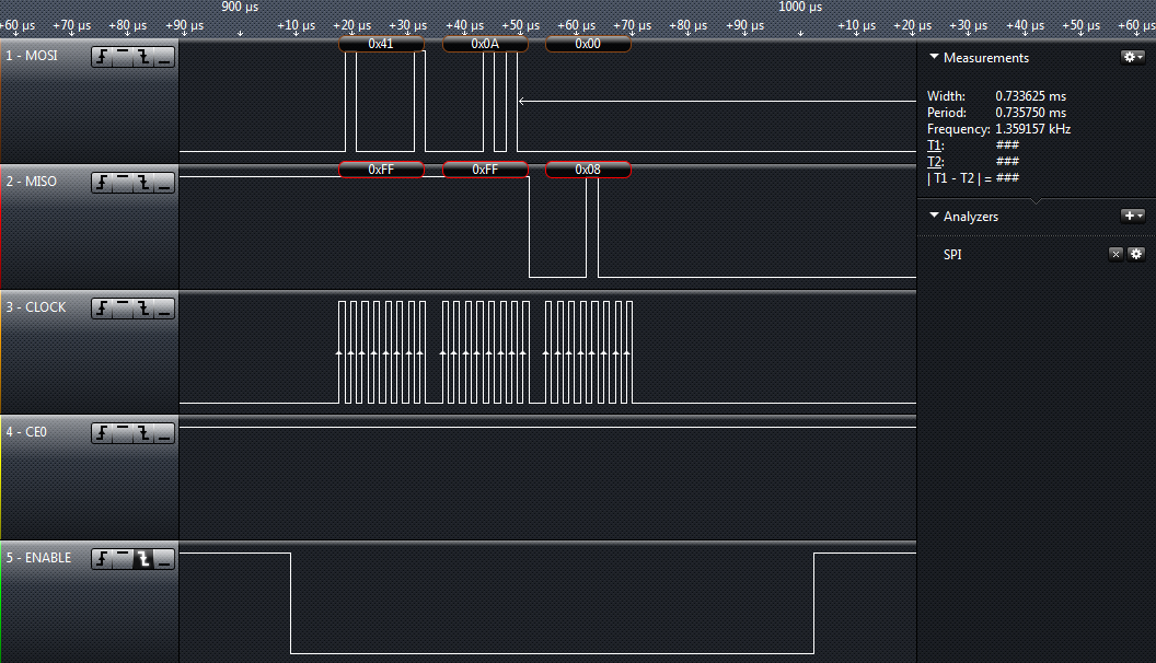
Now we are getting somewhere. The PFCAD is using CS1. Looking at the data being transferred, I see a chain of short groups of bytes:
0x40 0x0A 0x080x41 0x0A 0x000x40 0x00 0xFF0x40 0x0C 0xFF0x40 0x13 0x000x40 0x01 0x000x40 0x04 0xFF
Then quite a long gap (around 22ms) before we get to anything else. It seems quite likely that this is some sort of initialisation sequence, so lets try to send it from some other code and see what happens.
#include
#include
#include
#include
#include

#include

#define CHANNEL 1

void send3(uint8_t a, uint8_t b, uint8_t c) {
  uint8_t buf[3];

  buf[0] = a;
  buf[1] = b;
  buf[2] = c;
  wiringPiSPIDataRW(CHANNEL, buf, 3);
}

void main(int argc, char** argv) {
  if (wiringPiSPISetup(CHANNEL, 4000000) < 0) {
    fprintf (stderr, "SPI Setup failed: %s\n", strerror (errno));
    exit(errno);
  }

  printf("start\n");
  send3(0x40, 0x0A, 0x0B);
  send3(0x41, 0x0A, 0x00);
  send3(0x40, 0x00, 0xFF);
  send3(0x40, 0x0C, 0xFF);
  send3(0x40, 0x13, 0x00);
  send3(0x40, 0x01, 0x00);
  send3(0x40, 0x04, 0xFF);
  printf("done\n");
}
This is a fairly simple piece of C code, using Gordon's WiringPi library to do the low-level SPI twiddling, but I was impressed to see that it had some effect. It switched off the back-light on the PFCAD display! This is more than I managed in a day of code autopsy and head scratching.
I could keep on with this approach, and transcribe all the rest of the bytes I saw on the SPI bus, but I would prefer to work at a slightly higher level. So I need to work out what these mean. This means dipping into the MCP23S17 datasheet.
From the documentation, the MCP23S17 expects three-byte sequences of the form OPCODE REGISTER VALUE. OPCODE varies according to which MCP23S17 is being addressed, but in this case 0x40 is WRITE and 0x41 is READ. I'm not sure at the moment what the PFCAD software is doing with its write then read of register 0x0A, but I'm guessing it might be a check to see if the port expander is present and working. The others seem relatively straightforward, though.
| Register address | Register name | this value does |
|---|---|---|
| 0x00 | Bank A IO direction | all inputs |
| 0x0C | Bank A pull-ups | all pull up |
| 0x13 | Bank B GPIO data | all low |
| 0x01 | Bank B IO direction | all outputs |
| 0x04 | Bank A interrupt enable | compare against DEFVAL (reg 0x03) |
These seem to appear in a slightly strange order, but the intention is clear. The LCD is connected to bank "B", so the bank is set to output with initially low values. Bank A is set as inputs with pull-up resistors and default interrupt handling, so those are either unused, or connected to the PFCAD buttons.
One of the Bank B data lines is obviously connected to the back-light input on the HD44780, so when they are all set low, the backlight switches off.
I think that's enough detective work for now. I'll see how much further I can get another time!