A few months ago I got somewhat stuck trying to understand how to join the dots between the Bus Pirate and a MCP3002 SPI analogue to digital converter (ADC) chip. Finally I abandoned the effort and moved on to other things. More recently, however, I have succeeded in sending data to a MAX7219 LED matrix over an SPI connection", so I now feel that I have a better idea of what it all means. It’s time to have another go at reading analogue values using the Bus Pirate. And if that works, I’ll try with the Raspberry Pi (which was actually my intention all along!).
Much as I did with the MAX7219, I’ll start by gathering some useful links:
The connections are largely similar to the ones for the MAX7219. It’s the same essential interface, although the names of the pins on the MCP3002 package are slightly different again.
| Bus Pirate | MCP3002 pin | MCP3002 name |
|---|---|---|
| 5V | 8 | Vdd |
| GND | 4 | Vss |
| MOSI | 5 | Din |
| MISO | 6 | Dout |
| CLK | 7 | CLK |
| CS | 1 | CS/SHDN |
For initial testing, I connected the channel 0 analogue input (pin 2) to a voltage mid-way between 0 and 5V (set with a simple resistor divider on a breadboard) so that I could look for repeatable values rather than just noise.
Unlike the MAX7219 which has a convenient fixed two-byte data word, the MCP3002 is more of a binary device. According to the datasheet the device expects a single high start bit followed by three configuration bits (one bit for single-ended or differential, one bit to select which channel to read, and one to specify the bit order). The device then ignores (but still requires) following bits while it responds with a NUL bit (representing one clock of “thinking time”) followed by up to 10 bits of channel data.
For byte-oriented devices (such as the Bus Pirate and the Raspberry Pi), the data transfer really needs to be a multiple of eight bits. Unfortunately, adding up the above gives 1 + 3 + 1 + 10 which is only 15 bits. The datasheet recommends adding zeroes before the start bit where such padding is required, so the end result is:
- 0 – padding
- 1 – start bit
- 1 – single-ended mode
- 0 – channel 0
- 0 – MSB first
- 0 – NUL response bit
- 0000000000 – incoming data
As binary data for the Bus Pirate that would look like {0b01100000,0b00000000}. Note that this time I am using { and } brackets, as they show the result bytes.
For my first test I tried the above sequence and got some result data, but also an error. After a bit of fiddling around I came to the conclusion that the documentation does not quite match my Bus Pirate. The sequence seems to work better if I start it with { but end it with ]. However, even with no reported errors, I did not get the response I was expecting. The response data was always just 0. With a resistor divider on the input I would expect to get at least some sort of value, even if I have mis-configured the outgoing data. Despite trying a few other outgoing values, I still did not get anything useful. Time to find out what’s actually going on.
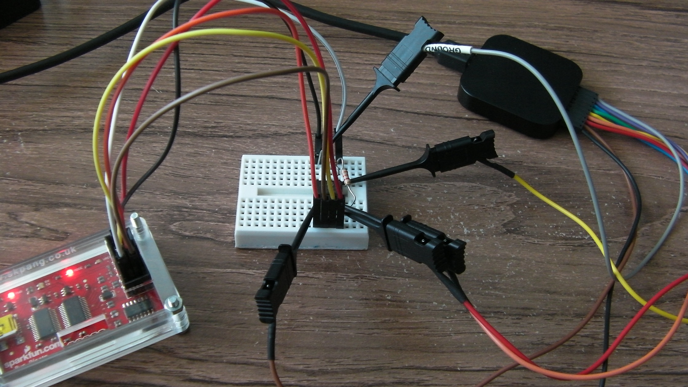
To take a look at the SPI signals in more detail I fetched out my Saleae logic analyser. This device has a enough brains to understand and decode several data formats, including SPI, so I connected clips to the appropriate pins on the MCP3002 chip, and took a look at the signals:
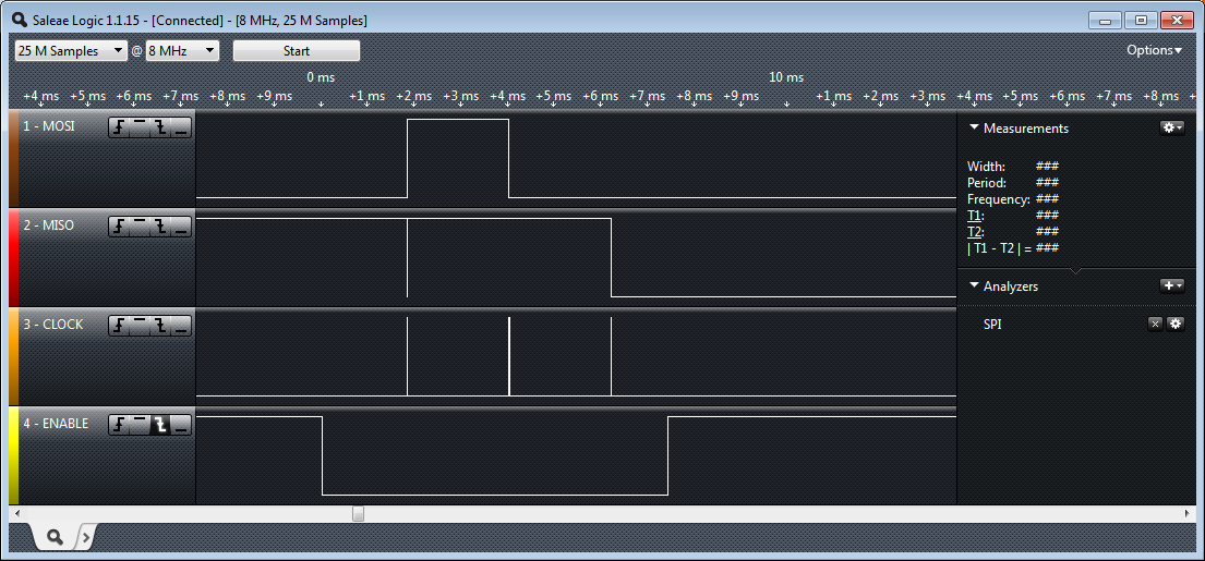
What I saw puzzled me. It looked a bit like the SPI diagrams in the datasheets, but not very much. The MOSI (data from Bus Pirate to the chip) seemed to either be all 1s, or to be only showing a single bit, and the clock waveform looked very strange. Oddest of all was the timings at the top. I had selected 1MHz (the fastest option on the Bus Pirate SPI configuration) which should have resulted in the clock cycling every 1 microsecond. Instead, it seemed to take a positively glacial 2 milliseconds between clock pulses! I tried resetting and re-configuring all the bits of the system, but to no avail. After a bit of searching around the web it appears that the firmware in some Bus Pirate boards has bugs which affect high SPI frequencies. There seems to be a way to update the firmware, but that’s one too many yaks for me to shave today. Tomorrow I’ll cut to the chase and try the MCP3002 on the Raspberry Pi.