For my next experiments with LEDs and PWM I need more lights. When I bought the "flowing water light" I also bought a second one, but I hadn't bothered assembling it yet. Naively I thought it would be as straight-forward as making the first one.
I assembled the board (as far as I can tell) exactly as I did with the other one a few days ago. However, when I tested it with the same Arduino "knight rider" program, I found that one of the LEDs was never lighting up. Initially I thought either the LED was faulty, or (more likely) I had soldered it in the wrong way round. Luckily, the kit included an extra LED, so I unsoldered and pulled out the dark one, then soldered in a fresh LED, making sure that I had it the right way round. It made no difference.
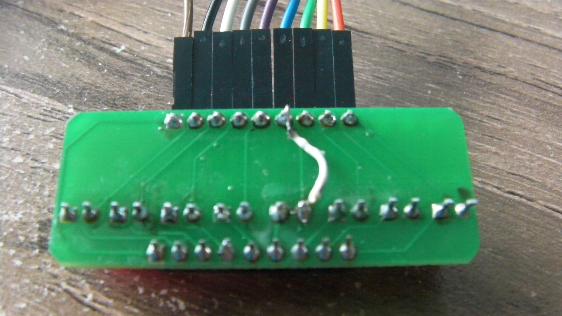
While soldering, I did notice that it was a bit tricky to get a good joint on one of the LED pins, so I took a closer look. There was definitely something a bit odd about that PCB track, which looked very thin and a bit tarnished. I gave in and replaced the questionable track with a bit of bridging wire between the input connector and the LED. Now all the LEDs work as expected.
As a bonus, I can now tell the difference between the two boards!