Although yesterday's post was a reasonable introduction to bit-angle PWM, showing a pattern of characters on a console screen is hardly the most exciting or useful thing. So today I shall try to use the same code to drive something a bit more fun.
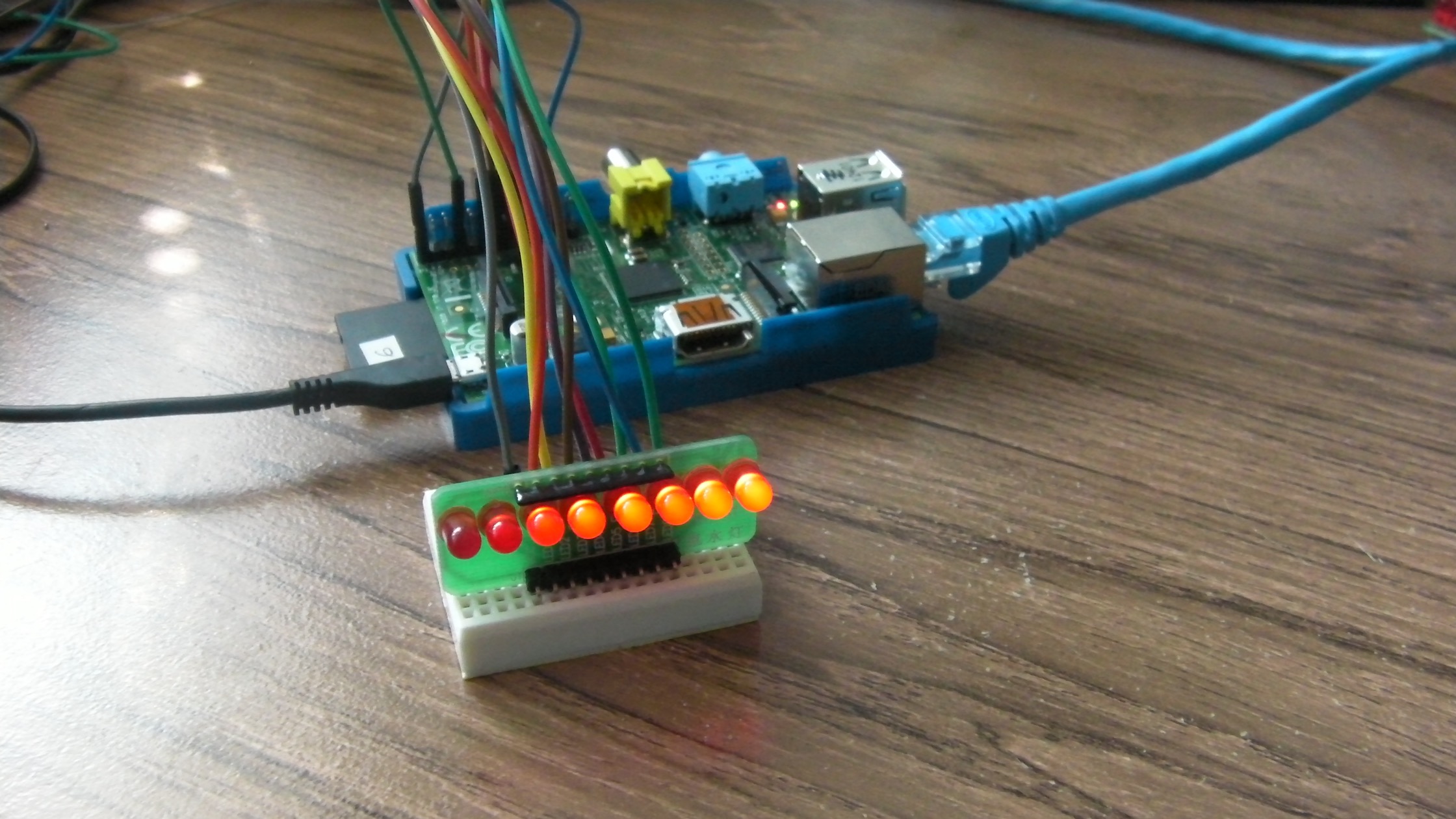
I still had the "flowing water light" lying around, which I had used to make a knight rider light with an Arduino. I connected it to GPIO pins 0-7 on the Raspberry Pi, If you don't have a convenient module like this, you can make your own with eight LEDs and eight resistors on a breadboard. I tweaked yesterday's PWM code to use WiringPi to switch the GPIO pins on and off instead of writing to the console. I also increased the PWM range to 6 bits (0-65) to give a bit more detail to the levels.
#include
#include
#include
#include

#define BITS 6
#define TICK_US 250

#define N_CHANNELS 8

extern int usleep(int usecs);

int levels[N_CHANNELS];
int state[N_CHANNELS];

void switch_on(int channel) {
  if (!state[channel]) {
    digitalWrite(channel, LOW);
    state[channel] = 1;
  }
}

void switch_off(int channel) {
  if (state[channel]) {
    digitalWrite(channel, HIGH);
    state[channel] = 0;
  }
}

void wait(int ticks) {
  usleep(ticks * TICK_US);
}

void emit() {
  int bit;
  int power;
  int channel;

  for (bit = 0; bit < BITS; ++bit) {
    power = 1 << bit;
    for (channel = 0; channel < N_CHANNELS; ++channel) {
      if ((levels[channel] & power) > 0) {
        switch_on(channel);
      } else {
        switch_off(channel);
      }
    }
    wait(power);
  }
}

void setup(int argc, char**argv, int* channels) {
  wiringPiSetup();
  for (int i = 0; i < N_CHANNELS; ++i) {
    pinMode(i, OUTPUT);
    digitalWrite(i, LOW);
    state[i] = 0;

    if (i < argc-1)
      channels[i] = atoi(argv[i+1]);
    else
      channels[i] = 0;
  }
}

int main(int argc, char**argv) {
  setup(argc, argv, levels);
  pinMode(0, OUTPUT);

  for (;;) {
    emit();
  }
}
To build this code, use: c99 -o gpio-demo gpio-demo.c -lwiringPi. To run it, use sudo ./gpio-demo with up to eight PWM proportions (in the range 0-63). Human perception of PWM LED light levels is not linear, and I found that sudo ./gpio-demo 62 61 60 59 58 57 56 55 gave a visible gradient. It happily drove 8 channels of independent PWM using less than 1% of the available CPU power.
While this does demonstrate the ability to generate PWM, it's not really very useful. The code enters into a loop in which it keeps checking whether it should change the status of the pins it is managing, but this prevents it from doing anything else (including from changing the PWM levels on the pins). A useful application would allow the "foreground" code to respond to inputs and make decisions, all while the PWM management is running in the "background". That's for another blog post, though.

I read somewhere that servos are usually controlled using PWM, so just to see if it would work, I connected the power and ground leads of a servo to the power and ground on the Raspberry Pi header, with a flying lead connected to the signal pin. I connected the signal pin of the servo to each of the outputs in turn and saw some servo-like behaviour, but most of the PWM levels that this code can generate are way outside the operating range for a servo, so that needs a bit more specialised software.