After thinking about how to drive the MAX7219 LED array I built yesterday, it occurred to me that maybe this is an ideal time to get to the bottom of how to use the Bus Pirate board that I failed to use with a MCP3002 ADC chip. This time I was determined to get it working.
To get started, I searched around and found the most important documents I need:
To get started I needed to make sure I could talk to the Bus Pirate, so I plugged it in to a nearby USB port on my Windows PC. It set itself up as a virtual COM port. I then opened a connection to the serial port in MobaXterm. Pressing "enter" a few times had no effect, so I went back to the Bus Pirate UI docs and found that the board expects an initial connection at 115200 baud. I changed the terminal speed and re-started the connection and got a nice Bus Pirate HiZ prompt.
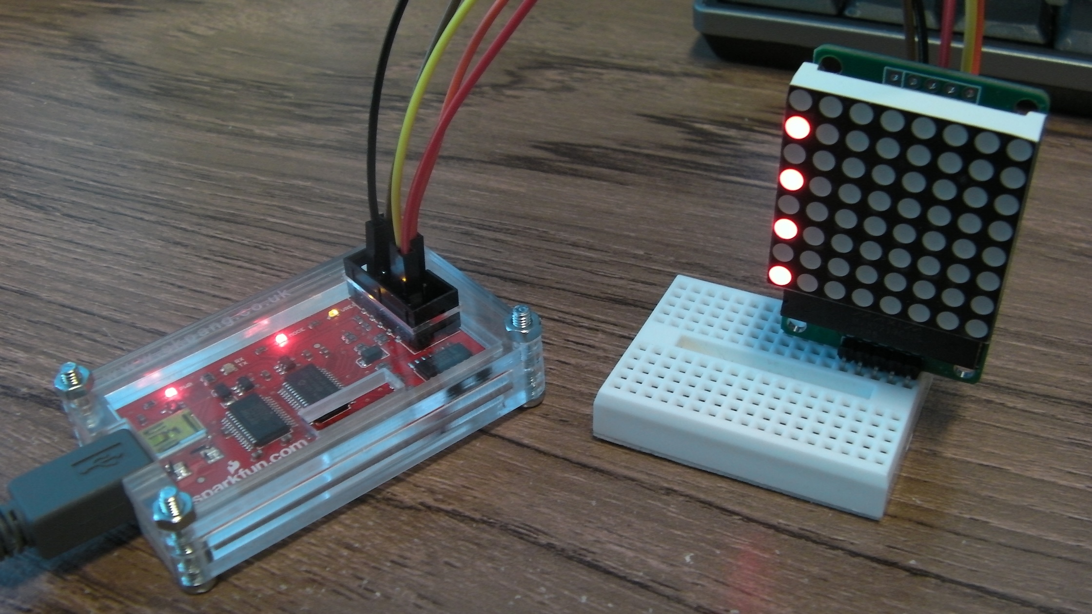
Having verified that I could talk to the Bus Pirate from the PC, I disconnected it from the PC and started to wire it to the LED board. My initial plan was to connect wires straight form the Bus Pirate pins to the header on the LED board. However, both headers had pins rather than sockets, and I could not find any wires with a socket at both ends. I had, however, bought a bundle of wires with a socket at one end and a pin at another, so it was straightforward to run the wires from the Bus Pirate pins to a little breadboard, into which I also plugged the LED board. This turned out to be quite useful, as it provided a kind of stand for the display and kept everything neat.
I wired the pins as follows:
| Bus Pirate | LED board |
|---|---|
| 3.3V | Vcc |
| GND | GND |
| MOSI | DIN |
| CLK | CLK |
| CS | CS |
I connected the Bus Pirate to the PC again and started to explore, with the help of the Bus Pirate UI guide. The obvious step was m to enter the menu, then 5 to select SPI mode. After that I tried sending some 0x00 and 0xFF values to the board which at least showed that the connection was working, as sometimes all the LEDs would light up and other times they would all go off. Hardly very useful, though. Time to hit the MAX7219 datasheet.
It took me a bit of time to get my head around this bit, as it seemed that the datasheet was filled with stuff I am not interested in (electrical and timing characteristics etc.), but very light on what data you need to send to the darned thing. Eventually through a combination of sending values to try things out, and going back and forth in the datasheet, I managed to work out what to do. So here's a summary.
First, note that the MA7219 expects 16-bit control words, which must be sent as two bytes using the Bus Pirate, so every command below is of the form [0xnn,0xnn]. The starting and ending brackets represent the setting of the CS line to tell the MAX7219 that there is data.
The MAX7219 is a register-based device. It has 16 addressable registers which serve both general purposes such as overall brightness, and a place to put the data for each column of the display. In every message to the MAX7219 chip, the low 4 bits of the first data byte indicate which register to write, and the second data byte indicates the data to write to it. Not all registers use all 8 bits of the data value, but you need to send it anyway. As an example sending [0x04,0xFF] places the value 0xFF into register 0x04. This could equivalently be sent as [0xF4,0xFF], as the high 4 bits of the register byte are ignored.
Once I worked out the register structure I could now see why my random set of 0x00 and 0xFF values had sometimes switched the whole display on and off. The chip has a "display test" register (0x0F). Setting data value 0xFF into this register switches all the LEDs on, and setting value 0x00 switches them all off. I could now repeatably send the two bytes [0xFF,0xFF] to switch all on, and [0xFF,0x00] to switch all off.
Getting to the next stage, where I could write my own data to the display turned out to be a bit more complicated. I don't know whether the chip always starts up with everything disabled, or whether it was just luck on my part, but I found that in order to get things fully working I needed to send:
[0x09,0x00]to switch off character decoding[0x0B,0x07]to enable all columns (without this only the first column worked, which confused me for a bit)[0x0A,0xFF]to set intensity to maximum[0x0C,0x01]to enable the display
At this point the display showed what appeared to be a random pattern. This pattern went away when I wrote my own data to the column registers. If you don't like this appearing, then I guess you could write your initial data to each column before using [0x0C,0x01] to show what's there.
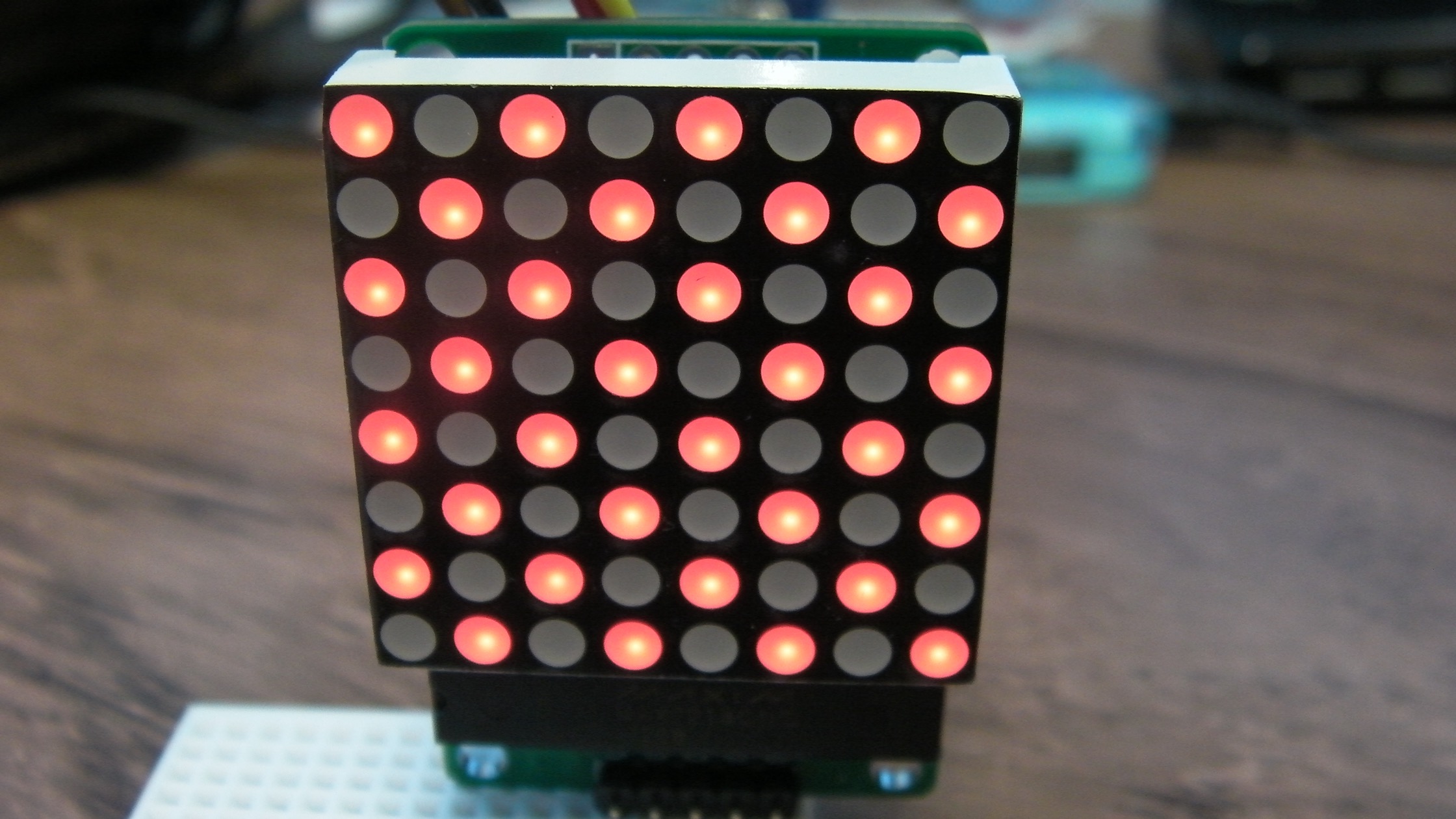
I decided to write data to columns to make a checkerboard pattern:
[0x01,0x55]
[0x02,0xAA]
[0x03,0x55]
[0x04,0xAA]
[0x05,0x55]
[0x06,0xAA]
[0x07,0x55]
[0x08,0xAA]
Now I know the sequence of bytes I need to write to the device to make it do stuff, the next step is to talk to it from a Raspberry Pi. I'll save that for another time, though.