I have had a kit of parts for a RaspiRobot board in my "to do pile" for a while now. Today I had a bit of spare time so I followed the construction instructions and put it together.
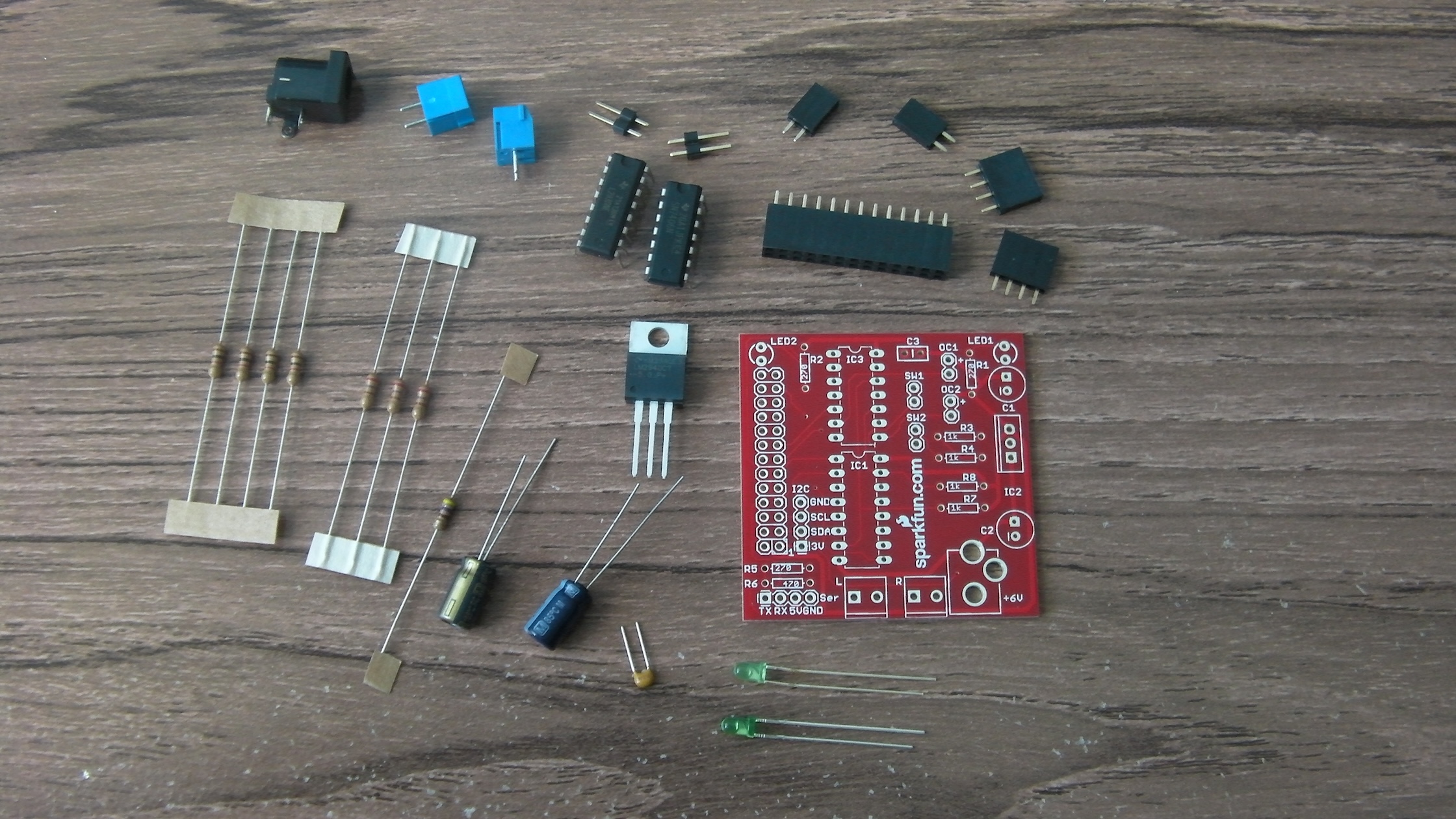
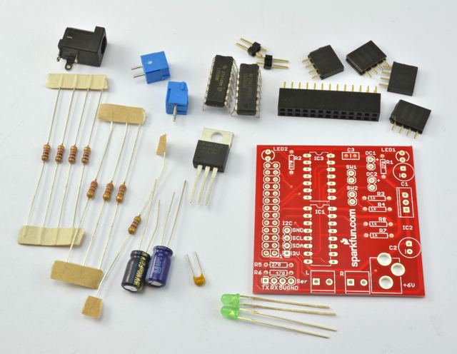
Step one was to check I had the right bits. I opened the packet and laid the components out just like the helpful picture on the website. Mine were different! The official picture shows four 4-way headers, whereas the set I got had two 4-way and two 2-way. A bit further down the page is a list of components, and that did agree with what I had received. Shame about the picture, though.
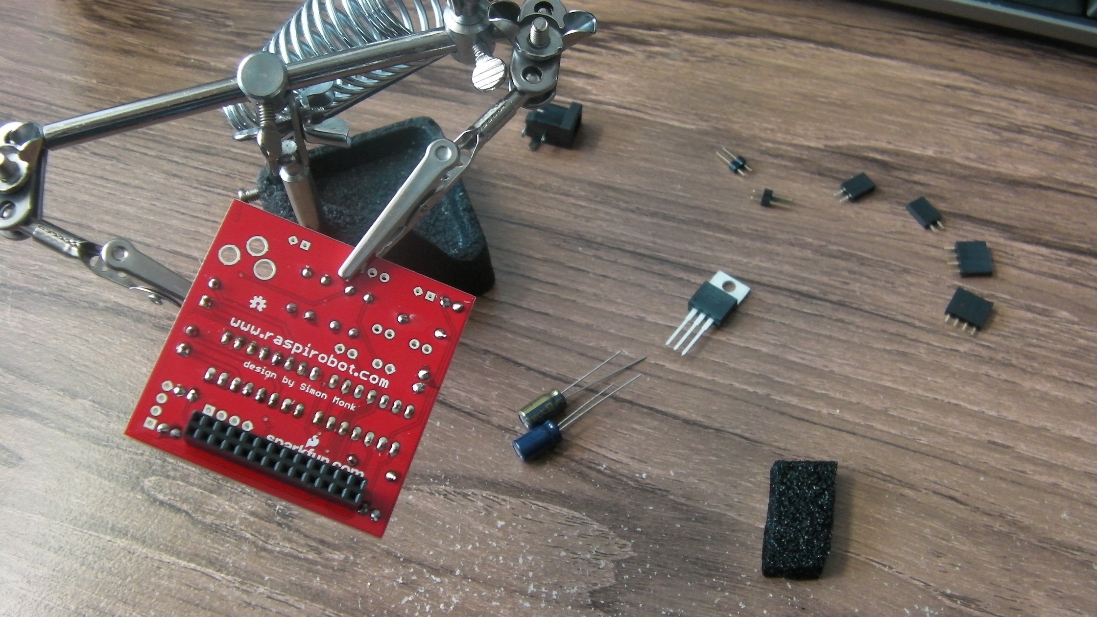
Once I had sorted that out I began assembling the board, with the help of my "third hand". Soldering it was very straigtforward, and all the components fitted nicely into their allotted places.
After construction, I was keen to test it. First of all I plugged it in without any motors or power supplies connected and followed the Getting Started tutorial
Once I had installed the various python stuff it requires, I was able to switch the two LEDs on and off. The instructions for switching the motors and open-collector outputs had no effect, of course.
Next, I tried to drive a motor. This is, after all, what the board is supposed to be for - if all I wanted was to switch two LEDs on and off I could have done it much more simply! This, however was where I hit problems. So far I have not been able to get the board to actually drive a motor. From reading the comments on the RaspiRobot sparkfun page it seems likely that the problem is one of power.
My first attempt was to try using USB power from the Pi. Nothing. But I half expected that - motors can take a lot of power, so the board provides a separate power input to drive the motors and (via a regulator) the Raspberry Pi. The web site says anything from 7-12V will do, so I tried a spare 12V power adaptor which I had lying around and happened to have the right kind of plug. It tested OK with a voltmeter, but did not seem to have enough juice to power up the Pi. Still, it only claimed an output of 400mA, so I tried a bigger one. 500mA was enough to half-start the Raspberry Pi, but not enough to boot the OS. I was sure a 1A adapter would be enough, but this didn't work either. All that happened was the regulator on the RaspiRobot board got very hot.
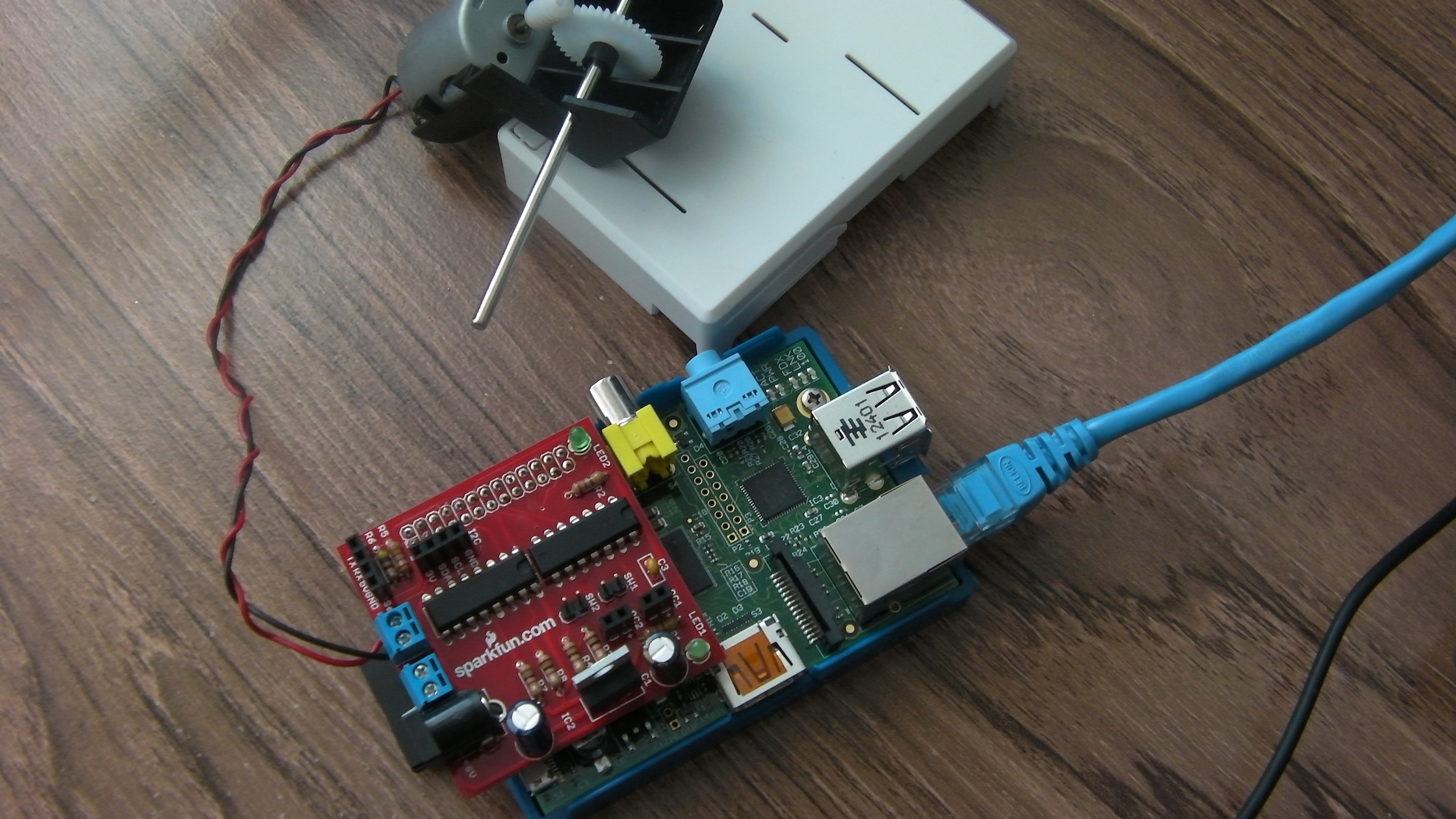
I know the motor works, because connecting it directly to the power adapter makes it spin happily. The problem definitely seems to be in the power handling on the RaspiRobot board.
I'll shelve this for now, and see if I can find anything else to power this board another day.