I recently got a comment on my article from 1st February about Soldering a Slice of Pi/O asking for some help in programming it in Python. This reminded me that I have not got very far with this little board beyond checking that the Raspberry Pi could see it. So I decided to see what I could find and if I could make it do something.
My first port of call was to look around the web. I quickly found several pages about the board and its key component, the MCP23017 i2C Expander chip.
- The datasheet for the chip is here
- Construction and fitting instructions are here
- A general discussion of i/o expansion using these chips can be found here
As far as writing programs to control the pins, though. That was a bit harder to find.
There is quite a nice article about controlling the MCP23017 chip here. Mid-way down the page it gives some examples of controlling the ports using i2ctools. If you followed the steps given in the construction guide above, or in my original article, you should already have these tools installed so, for example, you can do:
i2cset -y 0 0x20 x00 0x00
i2cset -y 0 0x20 0x12 0x01
sleep 1
i2cset -y 0 0x20 0x12 0x00
to switch A0 (that's the pin nearest the Raspberry Pi GPIO header) on for a second, then off again.
I hadn't quite realised until I started this that the IO headers on the Slice of Pi/O board are in two distinct rows. The outside row is all GND, and the inside row contains the actual GPIO pins. There are also two pin numbering schemes in use. The chip documentation numbers the pins as two banks of eight, named A0-A7 and B0-B7. They are separated into two banks for practical reasons to do with addressing. i2c software, however, typically seems to refer to the pins as a single run from 0 to 15. Just to clear up any confusion A0 is pin 1, A7 is pin 7, B0 is pin 8, B7 is pin 15. The pins run in ascending order from the end of the board with the Raspberry Pi GPIO header. Pin 0 (A0) is nearest the header, and Pin 15 (B7) is farthest away.
Programming the pins in a shell script is all well and good, but what was asked for was a way to program the pins in Python. This needed a bit more looking around. Eventually I found that some excellent teaching examples at Adafruit, in particular this one about programming the MCP23017.
If you are already comfortable with programming in Python on the Raspberry Pi, then the code example available from that page may be all you need to get started. I have not done much of this, though. Most of my Raspberry Pi programming has either been in C or in Ruby.
To give the Adafruit examples a try, I decided to have a go at installing and using the Python Web IDE. Installation was pretty simple: just follow the instructions at Adafruit.
The example code provided is OK for checking that everything is in place, but "out of the box" it just reads and prints the value of pin 3, then flashes pin 0 on and off as fast as Python will go. This is not very easy for an ordinary human being to spot.
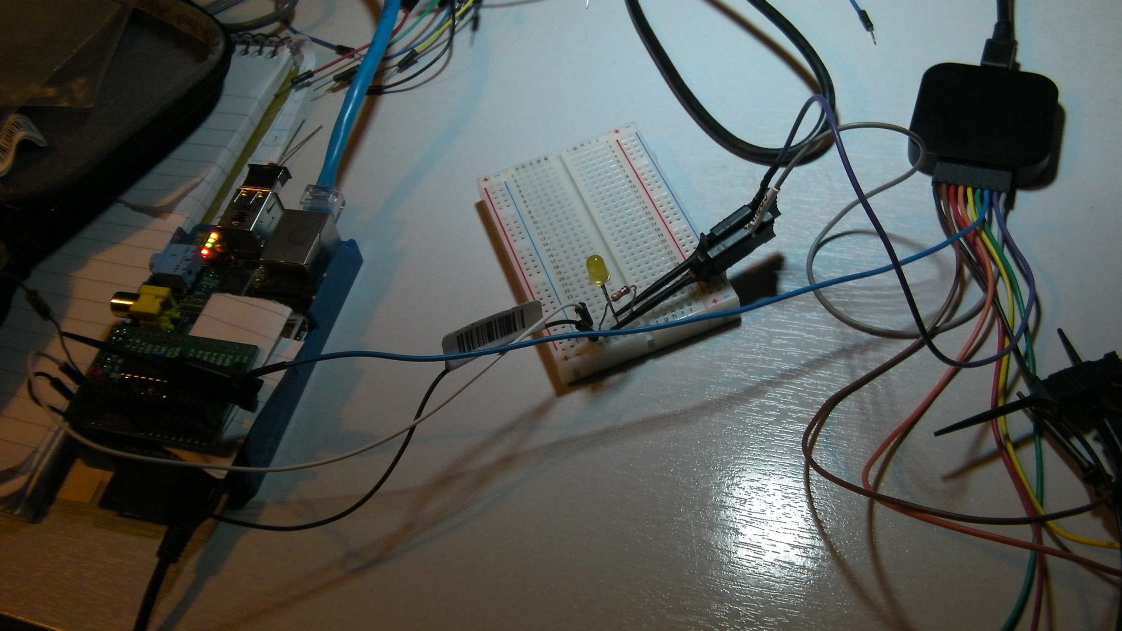
To make things a bit more visible, I wired an LED with a resistor in series between pin 0 and GND, then put a one second sleep between the flashes:
import time
    while True:
        mcp.output(0, 1) # Pin 0 High
        time.sleep(1)
        mcp.output(0, 0) # Pin 0 Low
        time.sleep(1)
At first I thought it was not working, but then I realised that the problem was in my choice of resistor. I had picked one with too high a value, so the LED was very dim. But when I turned off the room lights I could just about see it flashing.
Flushed with success I decided to do something a bit more interesting, and upgraded the code to cycle round three different pins "flashing" them in sequence:
    pins = [0,1,2]
    t = 1

    while True:
        for pin in pins:
            mcp.output(pin, 1)
            time.sleep(t)
            mcp.output(pin, 0)
            time.sleep(t)
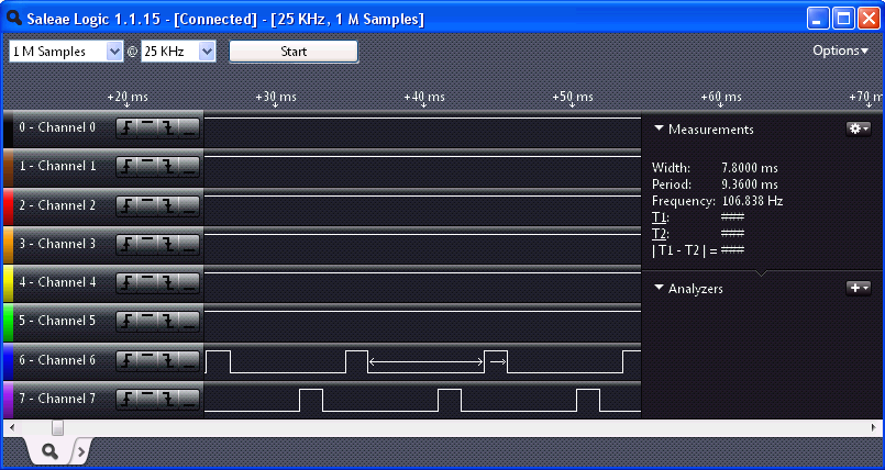
Trying to do this with my poor selection of resistors and LEDs was not very satisfactory, so I used it as an excuse to break out my Saleae USB logic analyser. I'll have to write another post about this device, but for now, I connected two of its channels to pins 0 and 1, then decreased the wait time "t" of the above example to 0.001s. I got a lovely trace showing the pins rising and falling.
I think that's enough for now. I have seen the pins working from Python, both as inputs and outputs, which I think is what was wanted.
While looking I did find another likely looking example of this sort of thing, with Python code here. I've not tried this one, but if you do , please let me know how you get on.