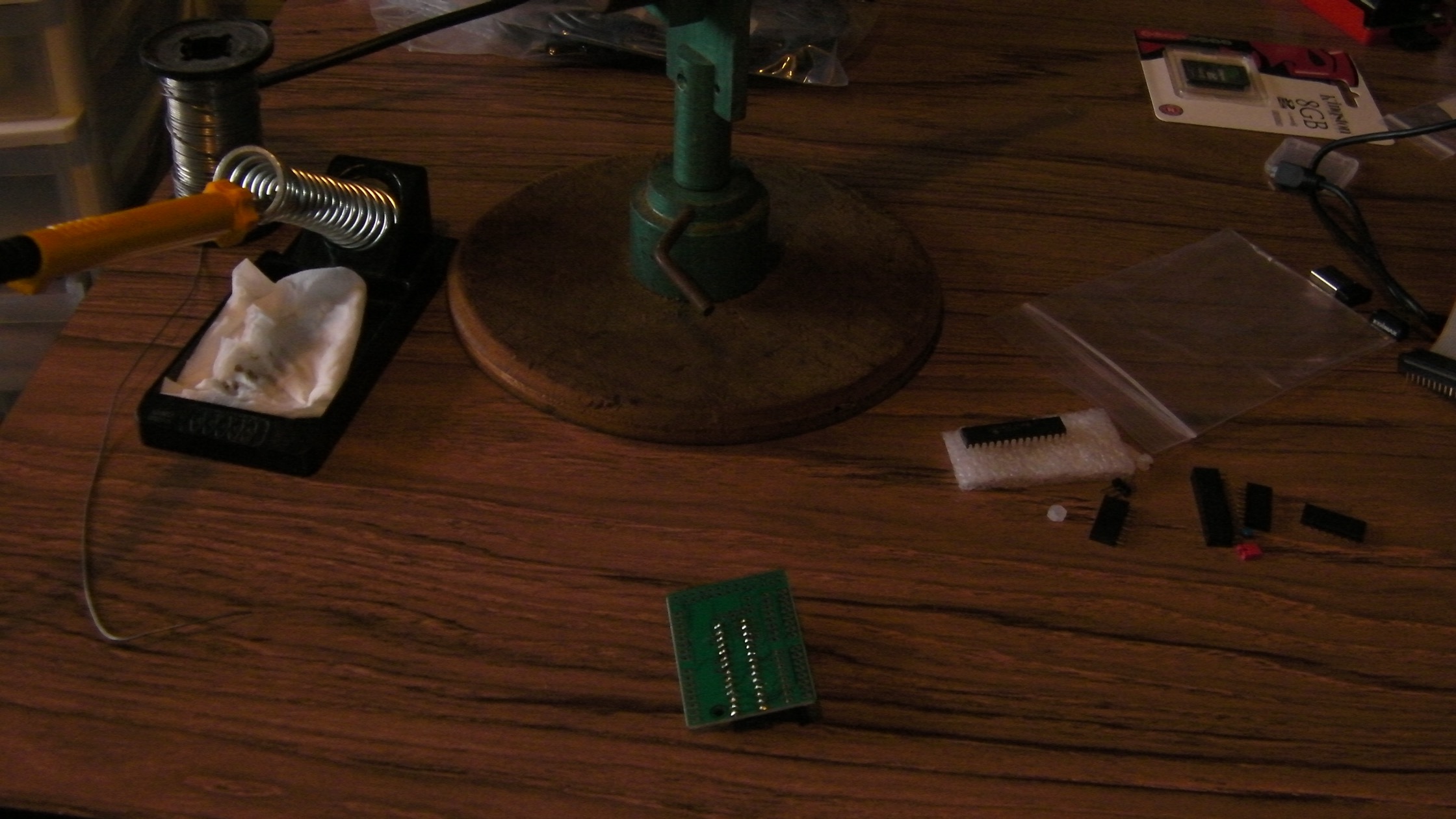
A few weeks ago I bought some interface adapter boards, including a Slice of PI/O, which came as a kit of parts in a little zip-lock bag.
I had a day off work today. Not for a good reason, unfortunately - it was my aunt's funeral in the afternoon. But it did give me an hour or so to do some raspberry Pi stuff in the daylight. As well as having a go at tidying up all the wires, SD cards and expansion bits I had lying around my desk, I fetched my soldering iron to assemble the Slice of PI/O.
I must point out that it is a long time since I last did any soldering. At the back end of the 1970s I used to do some hobby electronics (mostly projects from magazines, which I was rarely able to get working) and I was part of a three-boy-team who designed and built a robot lawnmower and got our 1 minute 55 seconds of fame on BBC TV's "Tomorrows World" show.
About a decade later I spent a few years working for a small electronics company. Although my main job was writing software, I did sometimes pitch in with bits of assembly or re-work. Since then, however, my soldering iron has remained cold and unloved. As you might imagine, it was with some trepidation that I set out on assembling this board. Luckily it is very simple to assemble, and most of the soldering is headers and sockets rather than components which might overheat or be damaged by static. The only real component which I had to solder was a little dipped capacitor, and they are pretty tough.
The main problem was a lack of hands - to get everything in exactly the right place, and get a really good joint, you need: one hand on the board, holding the component in place, one hand on the soldering iron to direct it to the right pin, and one hand on the solder reel to place the tip of the solder against the tip of the iron and the pin. A quick count shows that's three hands! This becomes even more complicated if you want to take a photo at the same time, so no action shots with a curl of smoke rising as the solder melts, I'm afraid.
I tried holding the board in a home-made vice, but holding the board still is not much use if the component jumps around in its holes as you apply the solder. Fairly quickly though, I got into the swing of the following steps:
- prop the tail of the solder so that it sticks in the air
- arrange the board and component in my left hand so that the component is aligned correctly and the pins are all visible on the solder side of the board
- touch the soldering iron against the tail of the solder so that it gets a 1-2mm blob of molten solder on the tip
- quickly move the soldering iron across to one of the end pins, and let the solder flow around the pin
- adjust the component while touching the iron against the solder if required until it is properly aligned
- repeat the solder blob technique for the opposite pin
- once the solder on the end pins has cooled the component should be held fast, and can be placed on the work surface and soldered using a more normal two handed method
- after all the rest of the pins are soldered, go along and inspect each one (especially the end pins), with a magnifying glass if it helps, to make sure that the solder is shiny and nicely shaped in a smooth curve from the pin to the board. If any of the joints looks dull or lumpy, or does not seem to have enough solder, melt it with the tip of the iron and add a little more solder. If any of the joints has too much solder, remove it with a wick or a pump, and try that pin again.
After soldering all the sockets, headers, and the capacitor, all that was left was to choose an address using the solder pads and then fit the MCP23017 IC.
Choosing an address was a bit of a head-scratcher. The instructions said how to do it, but did not really suggest a particular configuration, nor did they explain what the impact of choosing different settings might be. Eventually I opted for the low-low-low (address 0x20) option as shown in the picture.
Fitting Dual-In-Line ICs can also be tricky. As supplied, the legs always seem to bend outwards so that they are too wide for the socket. If you try and just wiggle or force the chip into the socket there is a high risk of bending or damaging some of the legs. In extreme cases this can mean you have to throw the whole chip in the bin. A trick I leaned years ago is to hold the IC horizontally in both hands with the pins facing away from you, then place the IC on the workbench and very gently roll it away from you, as if you are making a tortilla wrap, or a sushi roll. You only need to roll it a few degrees to bring the pins into a more reasonable line for insertion. Flip the chip over and do the same with the other row of legs and you should find it much easier to get it into the socket.
With everything in place it was time to attach the board to the Raspberry Pi. Another slightly nervous step. Although I'm pretty sure I soldered it right, I have blown up enough electronics with my overconfident tinkering in the past that it is always a concern.
The Pi booted into Linux fine, and I logged in over ssh to install the driver software. I had already enabled i2c on this SD, so the first step was sudo nano /etc/modules to add a line
i2c-dev
Next, get some i2c tools: sudo apt-get install i2c-tools and enable them for the default user with sudo adduser pi i2c.
The final step should be i2cdetect -y 0, but this gave
Error: Could not open file `/dev/i2c-0' or `/dev/i2c/0': No such file or directory
Looking back at the output, I'm guessing this is related to an error message which appeared during the apt-get:
Setting up i2c-tools (3.1.0-2) ...
/run/udev or .udevdb or .udev presence implies active udev.  Aborting MAKEDEV invocation.
A quick google search does now show me anything particularly appropriate to this problem. I tried a few things, including killing the udevd process with no luck. Eventually I rebooted the Pi and was then at least able to run the i2cdetect -y 0 command.
It's a bit tough to work out whether the results are what I should expect, though, as this is where the web instructions run out. What came back was:
pi@raspberrypi ~ $ i2cdetect -y 0
     0  1  2  3  4  5  6  7  8  9  a  b  c  d  e  f
00:          -- -- -- -- -- -- -- -- -- -- -- -- --
10: -- -- -- -- -- -- -- -- -- -- -- -- -- -- -- --
20: -- -- -- -- -- -- -- -- -- -- -- -- -- -- -- --
30: -- -- -- -- -- -- -- -- -- -- -- -- -- -- -- --
40: -- -- -- -- -- -- -- -- -- -- -- -- -- -- -- --
50: -- -- -- -- -- -- -- -- -- -- -- -- -- -- -- --
60: -- -- -- -- -- -- -- -- -- -- -- -- -- -- -- --
70: -- -- -- -- -- -- -- --
This does not seem very promising, as all the slots are empty.
Luckily a quick look at the reviews on the Ciseco product page for this board gave the answer. I'm running this on a rev2 raspberry Pi, so I need to use 12c channel 1. Entering i2cdetect -y 1 gave:
pi@raspberrypi ~ $ i2cdetect -y 1
     0  1  2  3  4  5  6  7  8  9  a  b  c  d  e  f
00:          -- -- -- -- -- -- -- -- -- -- -- -- --
10: -- -- -- -- -- -- -- -- -- -- -- -- -- -- -- --
20: 20 -- -- -- -- -- -- -- -- -- -- -- -- -- -- --
30: -- -- -- -- -- -- -- -- -- -- -- -- -- -- -- --
40: -- -- -- -- -- -- -- -- -- -- -- -- -- -- -- --
50: -- -- -- -- -- -- -- -- -- -- -- -- -- -- -- --
60: -- -- -- -- -- -- -- -- -- -- -- -- -- -- -- --
70: -- -- -- -- -- -- -- --
Looks like the board is detected, now I just need to find out how to use it. That seems as though it might be a more complicated task, so I'll leave that for another post.